Evolution of Hydraulic Prime Movers-Byron McCoy Web Page
EVOLUTION OF HYDRAULIC PRIME MOVER REACTION TURBINES
By Mr. Byron O. McCoy
Charles T. Main Company
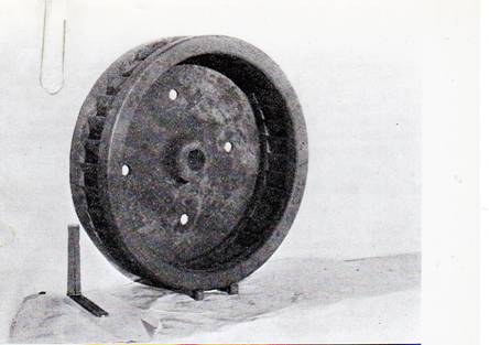
One hundred years ago, in 1852, we find that Samuel B.Howd of Geneva, N.Y. had patented an inward discharge hydraulic turbine. Transportation difficulties required licensed builders in their restricted localities to build and distribute the turbines in their restricted area. Therefore Howd's agents sold the rights for Middlesex County, Massachusetts to the Proprietors of the Locks and Canals on Merrimack River for about $1200 and this corporation sold permission to use a single wheel to Solomon Dutton of Sudbury, for $20. James B. Francis, Engineer for the Locks & Canals had become interested in the inward flow turbine of Howd and proceeded to improve it, getting the efficiency up to 79.3% (See Fig. 1).
Figure 1.
The specific speed was low, being about 19. Although Uriah A. Boyden had improved the Fourneyron or outward flow turbine and a large number of his turbines had been installed in New England, and although both the Boyden and Francis turbines were designed scientifically, the Francis turbine was the foundation on which the modern American turbine was built.
The so-called "cut and, try" period then set in from 1860 to a little after 1900. Instead of mathematical analysis and design, the wheel was generally left to the pattern maker to build, as he felt best for the flow of the water through it. If a wheel did not test up to expectations, its buckets were chipped back on the entrance or discharge edge, or its blades changed to a different shape until it showed better results. The various sizes were not homologous so that each size gave different results.
Asa M. Swain, a pattern maker of North Chelmsford, Mass. made his first 6-inch model in 1858. With a large diameter for its capacity (or a low specific speed wheel) much like the Howd- Francis except that its buckets were deeper, many in number and curved outward from the inner discharge edge, it was the direct predecessor of the modern low speed reaction wheel, The capacity was somewhat increased, on the advice of Mr. Hiram F. Mills in 1870 by deepening the entrance edge. By 1874, on a test of a 72-inch Swain wheel by Francis at the Boot Mills, an efficiency of almost 84%, with a specific speed of 40, was attained without a draft tube (See Fig. 2).
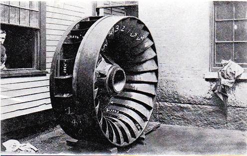
Figure 2.
Later on in 1909 C. M. Allen tested this wheel, after a draft tube and bevel crown gear had been added, and the efficiency on the jack shaft was 86.1%. The Swain wheels had very smooth water passageways and a diffuser was used at the discharge,
The first "American" water wheel, patented in February 1859 and tested by Emerson in 1872, showed an efficiency of 80%. Its specific speed was 25. This wheel was turned out by Stout Mills and Temple of Dayton, Ohio. Its capacity and efficiency was improved through various stages to the "Improved New American" wheel built by the successor company, Dayton Globe Iron Works.
James Leffel & Co. of Springfield, Ohio took out a patent in 1862 on a wheel with double decked runner. The upper runner was of the inward flow Francis type while the lower deck was of the inward and downward discharge type without band (See Fig. 3). It gave an efficiency of 74% and had a specific speed of 34.
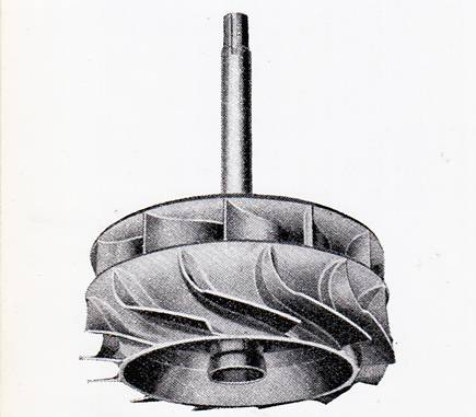
Figure 3.
Emerson tested out some very good wheels for Rodney Hunt Machine Company, Orange, MA presumably about 1875. A Hunt-Flint wheel with downward and outward discharge showed 90.5% efficiency at full gate, with a specific speed of 34.4. A test of a Hunt wheel with a specific speed of 35.1 and having downward discharge showed a full gate efficiency of 88%.
Of the low specific speed wheels, we should not forget to mention T. H. Risdon & Co., Mount Holly, N. J. who developed several high efficiency wheels (See Fig. 5).
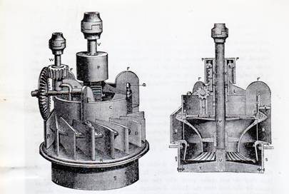
Figure 5.
One of them showed 91.32 efficiency at full gate and 73% at half gate. It is said that one wheel, with a diffuser, tested in 1873 gave 90.5% efficiency and 88.8% without it. The hydraulic design was considered excellent.
The "Victor" turbine as built by Stillwell and Bierce Manufacturing Co., Dayton, Ohio was simple in construction having an easily operated register gate and developed greater horsepower for a given size than any other turbine with the exception of the "Hercules" (See Fig. 7).
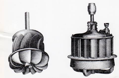
Figure 7.
A test on March 26, 1878 showed 88.08%, specific speed 46.2. Another test on October 29, 1878 showed 86.76% efficiency and a specific speed of 48.70. Platt Iron Works later on succeeded Stillwell & Bierce.
In 1876 several "Hercules" turbines as invented and layed
out by the well known pattern maker, John B. McCormick, and built by the Holyoke Machine Co., Holyoke, Mass, were tested and showed very good results (See Fig. 8 and Fig 8a.)
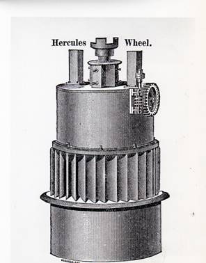
Figure 8
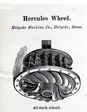
Figure 8a
One of them, in particular, showed 87% efficiency and "a power so extraordinary that the wheel was taken up (out of the flume) and. examined." A few changes were rather awkward. By 1890 the field for horizontal turbines was widened by their use for driving pulp grinders and the first horizontal generators. Multiple runner units with small diameter runners were used to obtain higher speeds. It was advisable to have them in multiples of 2 to reduce the load on the thrust bearing. If not of the open flume type, the turbines had plate steel cylindrical casings and the draft tubes were cylindrical without any flare. Apparently, the idea was to reduce cost regardless of efficiency. The draft chest consisted of a horizontal plate steel cylinder intersecting a vertical plate steel cone, which joined onto the draft tube (See Fig. 10).
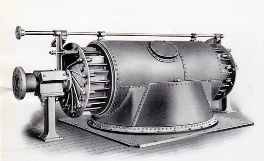
Figure 10.
In 1891, James Leffel & Company felt that in order to remain in the turbine business it would be necessary to develop a turbine that would equal or exceed the high results obtained by some of the competing turbines such as Victor, American, Success, Hercules, McCormick and others. At that time there were 42 other turbines on the market. Six different turbines were being built in York County, Pennsylvania. By 1897 Leffel had developed the Samson turbine, having a runner with double buckets and with a band on the bottom buckets. This wheel showed a maximum efficiency of 84.78% and a specific speed at full gate of 74.
Beginning in 1894 the Leffel Co. started to build six double discharge turbines for the two plants shown in Figure 11 at Niagara Falls, N. Y. These two plants were the first to develop the full head on the American side. It can be seen from the photograph that each of the prior installations was made for the maximum head that the turbine was capable of withstanding.
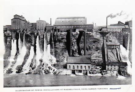
Figure 11.
Figure 12 shows the interior of one of the stations having four units, each of which has a generator at each end of the shaft.
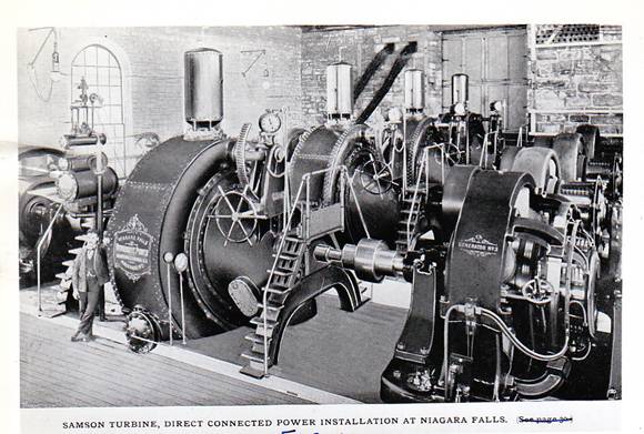
Figure 12.
Presumably at that time single generators could not be obtained of large enough capacity to take the full turbine output of 3,200 H.P. The speed was 160 R.P.M. Of course this was before the days of alternating current. It is interesting to note the air tank on the top of each turbine casing to absorb the surges.
Multiple runner installations, both the horizontal and vertical type, were used for most of the lower head developments until 1911. An extreme example of this was the installation in 1900 of forty 500 H.P. quadruplex horizontal turbines at Sault Ste. Marie, Mich. under 16 ft. head to drive electric generators. Twenty eight 885 H.P. additional units of the same type were installed in this plant in 1916 but with camel-back discharge cases of improved type, which when tested out at Holyoke showed 1% efficiency and 7% less power than a vertical setting.
Sextuplex horizontal units of 6,000 H.P. capacity were installed at the Sanitary District of Chicago, Lockport, Illinois and of 2780 H.P. capacity at the Kilbourne Plant of Southern Wisconsin Power Co. Several multiple runner vertical units were installed, such as at the Hales Bar Plant on the Tennessee River and Vernon Plant on the Connecticut River, but the largest in capacity were probably the five 13,500 H.P. units in the McCalls Ferry Plant on the Susquehanna River.
An outstanding runner of this period was the "Improved New
American" built by the Dayton Globe Iron Works, which tested
out about 88.1% efficiency with a specific speed at full load
of 79 to 80. In 1909, Wellman Seaver Morgan Co. obtained 90.4
efficiency at Holyoke of a runner with a specific speed of 59.
About 1906, Allis Chalmers Company built a horizontal turbine
to operate under 50 ft. head for California Gas & Electric Co.
and another horizontal turbine with the exceptionally low
specific speed of 10 for the Snow Mountain Power Co. in
California.
One of the highlights of American turbine design to be mentioned was the installation in Station 3A of The Niagara Falls Power Co. of thirteen 10,000 H.P. horizontal double -discharge turbines made by I. P. Morris Co. in 1908-1909. These units are still in operation.
Again in 1910 and 1911 Allis Chalmers designed and built two 22,500 H.P. horizontal double discharge turbines under 440 ft. head for the White River Plant of Pacific Coast Power Co. which were the largest in capacity up to that time (See Fig. 13).
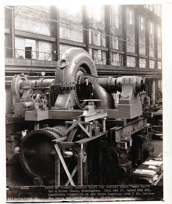
Figure 13.
The gradient of the penstocks down to this plant was so gradual that surge tanks open to the atmosphere would be too far away from the turbines to be effective. The Consulting Engineers, Stone and Webster, therefore decided and did use air tanks 75 ft. high just outside the power house with diaphragms to separate the air and water for surpressing the surges.
In the summer of 1911 the turbine manufacturers learned that High L. Cooper was engaged at Keokuk, Iowa in making a large development on the Mississippi River for the Mississippi River Power Co. At first multiple runner horizontal and vertical settings for the turbines were proposed. But it was soon realized, that with so much water to be handled, a radically different type of unit should be considered. This led into studies of single vertical turbines, concrete spiral casings and large curved type draft tubes, all of which seemed to work out well and the design appeared feasible with the possible exception of the thrust bearing. It was intended to use standard roller bearings under oil pressure.
The units were rated 10,000 H.P. each under 32 ft. head and 57.7 R.P.M., a synchronous speed for 25 cycles. In September 1911 Mr. Cooper was ready to let the contracts for 15 main turbines and two 2200 H.P. exciter turbines. The job had settled down to two bidders, I. P. Morris Co. and Wellman Seaver Morgan Co., who Mr. Cooper called in and said: "Now I'm going to split this job between you two bidders but I'm not going to give it to you at your price." After figuring the pound price of each bid and averaging the two, he said: "I realize that I am pioneering in going to these large units. I don't want to see you skimp the job so I'm going to give it to you both on this average pound price. But I don't want to see you load up the design where it is not necessary. I'11 be the judge of that when I approve the drawings." The two bidders were to agree on a common design with the exception of the runner. See Figure 14 and note the column bolts spanning the throat of the spiral casing, the crown plate in the form of an "A" frame to carry the load from the thrust bearing down to the column bolts through the upper curb ring.
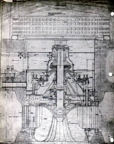
Figure 14.
One manufacturer could ship his runners in one piece on a special car but the other had to split his. Both builders earned a fine bonus as the efficiencies measured by field tests came out to about 90% with 83% guaranteed.
The Kingsbury type thrust bearing came onto the market as
the Keokuk turbines were being put into commission. Some of the roller bearings, if not all, were gradually replaced by Kingsbury bearings. These units have now been in operation 40 years without major repairs and should, without doubt stand up another 10 years---so it is not amiss to figure depreciation of large vertical hydro-electric units on the basis of 10 years use.
The next real large vertical units with outside gate mechanism were the nine built by the same two companies for the Cedar Rapids Development on the St. Lawrence River where the head was 30 ft., capacity of each unit 10,800 H.P. and speed 54.3 to 56.4 R.P.M. These units had speed rings spanning the throats of the spiral casings and they were larger in physical size than Keokuk. Due to the low speed and the heavy load of the 60 cycle generators, a severe thrust bearing problem was set up. This was a case where the Kingsbury type thrust bearings were replaced, by spring type bearings, when they had been offered by the General Electric Co.
Prof. Zowski of the University of Michigan
designed some
high specific speed low head runners for Allis Chalmers, S.Morgan Smith Co. and.
James Leffel & Co. between 1911 and 1914, which culminated in a wheel for the
latter company of 107.5 specific speed having an efficiency of 90.61%. By
1923--24 James Leffel & Co. and S. Morgan Smith Co. had developed, reaction
runners of 124 to 125 specific speeds with efficiencies slightly below 90%'. At
this same time fixed blade propellor turbines were being installed extensively
and were taking the place of high speed reaction wheels due to their higher
speeds with slightly lower part gate efficiency. S. Morgan Smith Co. introduced
into this country in 1927 the Kaplan adjustable blade turbine and sub-licensed
the other principal turbine builders under the patents so that due to its higher
specific speed and high efficiencies over the full range of load, it is being
used for run of the river installations and for heads up to 100 ft.
Record Efficiencies
The following developments were thought to have shown record high efficiencies at the date of installation:
The Niagara Falls Power Co. in 1919 installed three 37,500 H.P. turbines under 213.5 ft. head and operating at 150 R.P.M. The 2 units furnished by I. P. Morris Co. showed an efficiency of 93.3% on field test and the unit furnished by Allis Chalmers Mfg. Co, developed about the same efficiency. (see Fig 15.)

Figure 15.
Again, in 1923, the Niagara Falls Power Co. installed three 70,000 H.P. turbines under the same head, but to operate at 107 R.P.M., which were the largest in capacity to be attempted up to that time. By coincidence, the I. P. Morris unit tested gave the same efficiency as the Allis Chalmers turbine; namely, 93.8%. Figure 16 shows the turbine casing.
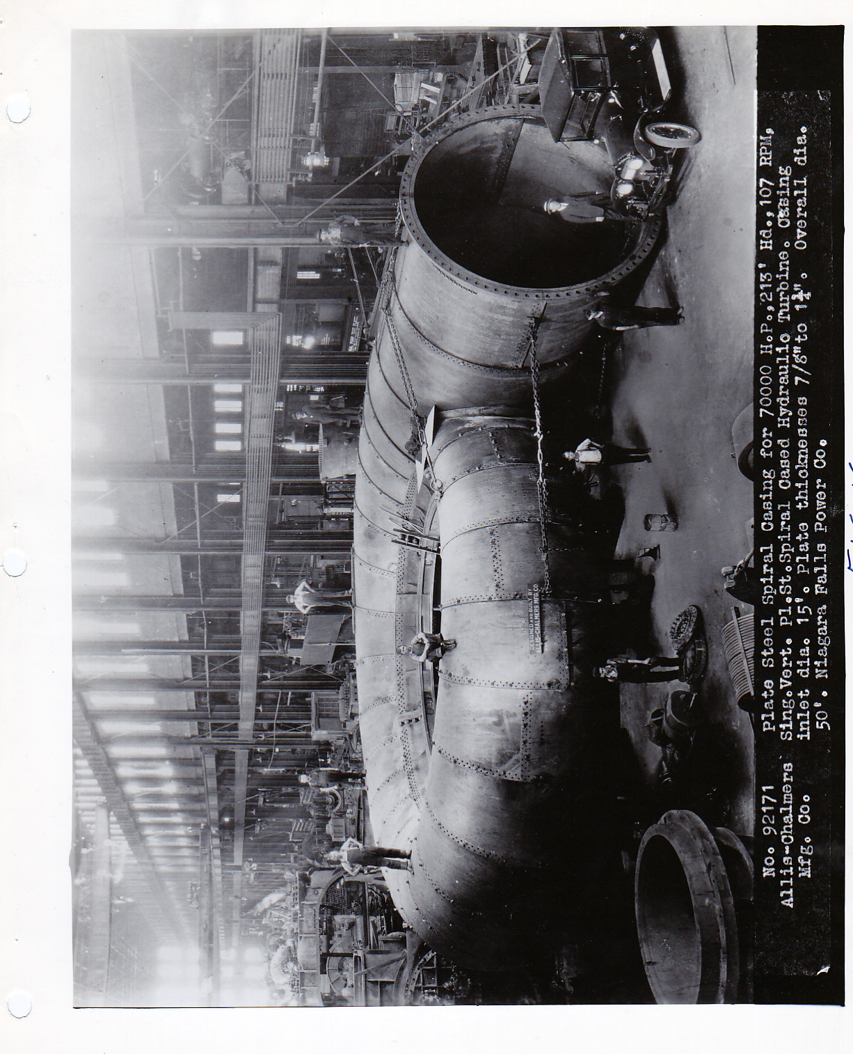
Figure 16.
In 1927, a Francis type turbine with a specific speed of 109 furnished by S. Morgan Smith Co. for the White Rapids Development of Northern Electric Co. on the Menominee River gave an efficiency of 93.7% on field test.
At the Saluda Development of Lexington Water Power Co., one of four 55,650 H.P. turbines under 180 ft. head and 138.5 R.P.M. built by S. Morgan Smith Co. gave a maximum efficiency of 94.6% in 1931.
A vertical turbine built by James Leffel & Co. for the
of Central Power & Light Company Eagle Pass Development/of San Antonio, Texas shored 93.9% efficiency on field test in 1932. The model runner had topped all Holyoke Tests with a maximum efficiency of 94.57%,
For many years the highest head development east of the Rocky Mountains, the Tallulah Plant of Georgia. Railway and Power Co., had five 19,300 H.P., 514 R.P.M. turbines under 580 ft. head, It was installed about 1913 and an efficiency of 90.4% was obtained on field test.
Southern California Edison Co. installed three 35,000 H.P. turbines under 740 ft. head in 1923, maximum head 820 ft. These turbines were built by the Wellman Seaver Morgan Company.
In 1924 Pelton Water Wheel Co. built for Portland Railway Light and Power Co. one 35,000 H.P., 514 R.P.M. turbine under 849, ft. head, maximum head 930 ft.
The S. Morgan Smith Co. furnished three 49,000 H.P. turbines under 755 ft. head for Carolina Power and Light Co. in 1927. Efficiency on field test 90.0%, maximum head 840 ft.
A 60,000 H.P. turbine under 925 ft. head and at 450 R.P.M. built for Nantahala Power and Light Co. by Newport News Shipbuilding and Drydock Co. and installed in 1942 deserves particular mention because of the following features:
1. The large radial gap between the tip of the wicket gates and the entrance edge of the runner, to prevent vibration.
2. Smallest possible diameter seal rings on crown and band of runner to provide minimum leakage and hydraulic balance.
3. Shaft in one piece and three bearings for the unit, the upper bearing on the generator being a spherical guide and thrust bearing.
4. Maximum efficiency attained on field test 93.7%.
5. Maximum net head 1,000 ft.
The highest head turbine built in this country was sent down to the Ixtapantongo Development of Comision Federal de Electricidad in Mexico in 1942. The turbine was rated 39,000 H.P. under 1028 ft. head and at 600 R.P.M. A second unit was built during the last World War.
Other than the turbines mentioned above, the following units are given as being the largest in capacity when they were built:
Two 61,000 H.P. turbines under 327 ft. head or 55,000 H.P.
under 305 ft. head for Hydro Electric Power Commission of Ontario 187.5 R.P.M. These units were built by Wellman Seaver Morgan Company in 1920.
Construction began in 1930 on two 83,000 H.P. turbines under 310 ft. head by S. Morgan Smith Co. for the Diablo Plant of the City of Seattle, Washington. The casing had to be split in eleven sections (see fig. 17).
Figure 17.
After installation it was found that these turbines produced 94,000 H.P. each under 327 ft. head.
In 1933 to 1934 A114c Chalmers Mfg. Co. began shipping out 115,000 H.P. turbines to Boulder Dam of 180 RPM for 60 cycle generation. The normal head was 510 ft. In all, Allis Chalmers furnished 12 units for this development. Starting in 1938 Baldwin Locomotive Co. began to ship the first of 5 turbines of this same rating. All of these 17 unity were for Southern California Edison Co.,
the City of Los Angeles, or the Bureau of Reclamation, California-Nevada. Power Co. though the Bureau took two 55,000 HP units from Newport News Shipbuilding and Drydock Co.
Near Spokane, Washington on the Columbia River, the Bureau of Reclamation layed out two power houues, one at each end of the Grand Coulee Dam, in each of which is installed 9 hydro-electric units. Each of the first nine units was rared at 150,000 H.P. Each unit in the second powerhouse was rated 165,000 H.P,, making a total rated capacity of 2,835,000 H.P.
Spiral casings of each of the first nine units are of cast steel, each in fifteen sections (See fig. 17).
The remaining nine spiral casings are of plate steel with cast steel f1anges and in fifteen sectitons with each section containing at least one stay vane. The casing inlet diameter is 15 ft. and the turbine runner diameter it 197 inches.
Work was started on the first turbine by Newport News
Shipbuilding and Drydock Co. In 1938 and the eighteenth turbine war completed by them in 1951. For a period during the War, no work was done.
Safe Harbor Water Power Corp. started negotiations in 1930
for 7 turbine units of 42,500 H.P. for their plant on the Susquehanna River. This resulted in the units being split up between the S. Morgan Smith Co. and the I. P. Morris Co. The normal head on these turbines is 55 feet and the speed 109 P.P.M.
Figure 18 shows a cross section of the units which had common design.
Figure 18.
From 1938 to 1942 ten 280" diameter Kaplan turbines were
built by the S. Morgan Smith Co. for the Bonneville Development of United States Army, Corps of Engineers (See Fig. 19 ).
Figure 19.
The first two units were rated 60,000 H.P, at 60 ft. head because of the limited capacity of the generators but the remaining turbines of the same size are rated 74,000 H.P. each, speed 75 R.P.M. Under order now by the same customer and with the same builder are fourteen 111,300 H.P. Keplan turbines under 80 ft. head, speed 85.7 R.P.M., for the McNary Dam, upstream from Bonneville on the Columbia River.