GREEN                                                

      AND

         CLEAN

                        POWER

French River Land Company's Website!


French River Land Company's Home Page!

Poetry of Power

FRL History

Hydrolec Disassembly

Hydrolec Rebuild

Key Personnel

Machine Shop

News Page

Previous Pictures

Previous Pictures Two

Previous Pictures Three

Previous Pictures Four

Bill Munch

Projects

Rebuilding 120" Niles Boring Mill

For Sale

HYDROELECTRIC SITES:

Alternatives Hydro

Anasagunticook Lake Dam Replacement-    C.Fay & W.Fay

Appleton HEP-Jim Lichoulas

Appleton Wisconsin Anniversary

Badger Pond Dam Removal

Senor Bonifettis' sites in Chile

Chittendon Falls

Claytor Dam

Collins Bascule Dam

ESAC WORKS      July 1985

Fiske Mill

1852 Fourneyron

Golden Pond Hydro

Harry Terbush Sites

Hunts Pond

Indian River Rebuild

Kaplans

Jaffery Fire Protection

Konkapot Creek

Lake May Pelton Wheel Removal

Livermore Falls

Martinsville Hydro

OSV

Shaker Mill Dam

Silk Knitters- Ron MacLeod

South Village Dam

Sparhawk Mills

Tannery Pond

Tannery Rebuild

Turners Falls Generator Rewind

Valatie Falls

Valley Paper

USEFUL ENGINEERING:

Admitting Air to Turbine Runners Improves Efficiency, S. Logan Kerr

Air Admission to Hydro Runners, David Cox, USCOE, Kerr Dam

The Banki Water Turbine Mockmoore and Merryfield

Barrel Stave Bearing Repair

Bishops Method- STABGM Program

Blade Design Kovalev

Blade Pitting- Boving LTD 1930

Cavitation- Accelerated Research, Allis Chalmers Research

Cavitation & Vibration of a Draft Tube

Cavitation- Prevention & Reduction, Allis Chalmers Research

Causes & Effects of Cavitation in Hydraulic Turbines

Chain Turbine by: Nguyen Minh Duy

Chain Turbine Mechanics- Discussions with Duy

Characteristics of Modern Hydraulic Turbines-Chester Larner

Comparative Tests On Experimental Draft Tubes- C M Allen & I A Winter  1923

Design of an Overshot Waterwheel

(by Carl Weidner)

Design of Pelton Buckets

Design of Small Water Turbines for Farm and Small Communities

Design of the runner of a Kaplan turbine for small hydroelectric power plants: Timo Flaspöhler

Draft Tube Design

Draft Tubes of Hydro-Electric Stations by M. F. Gubin

Draft Tube Tests

Ejection into Tailraces of Hydropower Plants: S. M. Slisskii

Erection & Alignment of Vertical Waterwheel Generator Units-R.O. Standing

Evolution of Hydraulic Prime Movers-Byron McCoy

Fall Increaser- Henry Ford

Fall Increaser Herschel Venturi Tube

Fall Increaser Moody Ejector Turbine

Fall Increaser Hydraulic Jump Apron

Flashboard Pins

Gatecase Design- Kovalev

Generator Shaft Design Calculation- Olav Hodtvedt

Governor Theory for the Plant Operator

Graphics of Water Wheels- William Fox

Hydraulic Motors- M. Bresse & F. A. Mahan 1869

Hydraulic Turbine and Governor Field Erection Information

Hydraulic Turbines- Robert Long Daugherty

Hydraulic Turbines by Arnold Pfau

Hydraulic Turbines Gelpke & Van Cleve

Hydrokinetic Energy in Massachusetts, William D. B. Fay

Hydrostatic Beam Analysis

Impulse Turbines  by Ely Hutchinson

Interference fitting a large runner shaft

Kaplan Blade Design NACA Air Foil- Report No. 460

Kaplan Blade Design NACA Air Foil- Report No. 628

Kaplan Design- Kovalev

Kaplan Design Marko Kogovsek.xls

A Laboratory Study to Improve the Efficiency of Crossflow Turbines- N. Aziz & V. Desai

Low Head Hydroplants, Emil Mosonyi

Meggering Generators

Meggering      Earth Resistance

Motors as Generators for Microhydro, Nigel Smith

Miroslav Nechleba

Natick Dam Powerhouse Calcs

Operation & Maintenance of Hydro-Generators

Out Gassing of Cross Flow Turbines

Parallel Operation of Turbines Analysis

Pelton Design- Daugherty

Powerhouse Design- Miniwatt Hydro

Powerhouse Design- Natick Dam

Power Plant Inspection

Rake-Leonard

Rake-Newport News

Rack Design-Chicopee-Olav Hotvedt

Rack Design- PHI- Bill Fay

Rack Design-PHI-Brian French

Rack Design-PHI-Ken Smith

Rack Design-ASCE

Rack Design- Hydraulic Institue of Munich

Rack Design-Flow Induced Vibrations

Rigging a large generator

Selecting Hydraulic Reaction Turbines BUREC

Shafts- Kovalev

Shaft Couplings

Snows Improved Water Wheel Governor

Standard for Hydraulic Turbine and Generator Shaft Couplings and Shaft Runout Tolerances

Stoplog Design Calculation

Stoplog Structure Design Calculation

Stress Analysis of Hydraulic Turbine Parts, BUREC- F.O. Ruud

Some Fluid Flow Characteristics of a Cross Flow Type Hydraulic Turbine- Durgin & Fay

Tenth Census of the US, 1880, Water Power of the US, Part I- Professor Trowbridge

Tenth Census of the US, 1880, Water Power of the US, Part II- Professor Trowbridge

Tests on a Kaplan Hydraulic Turbine

Theoretical Conditions Related to an Open Channel Flow Linear Turbine- Ishida & Service

Theory of Turbines- De Volson Wood

Treatise relative to the Testing of Water-Wheels and Machinery, James Emerson 1879

Trash Rack Differential Equations 2L/3

Trashrack Differential Equations General Solution f(x)

Turbine Water-Wheel Tests- Robert Horton

Turgo, A High Speed Impulse Turbine- Paul Wilson

Vortices at Intakes

Water Hammer-Lorenzo Allievi-Text

Water Hammer-Lorenzo Allievi-Figures

Water Hammer-ASME Symposium 1933

Water Hammer _ Norman Gibson

Water Hammer-E.B.Strowger

Waterpower Engineering-Daniel Webster Mead

Water Turbines Contributions to Their Study, Computation and Design-S.J. Zowski

Water Wheel Design- Ken Smith

Weights

WHAMO

White Hydraucone Regainer

Wooden Penstocks

TRADE CATALOUGES:

Bradway Turbine  (progressive gate)

C.P.Bradway Turbine

Brook Waterwheel

Charmilles Turbines

Christiana Machine (register gate)

Dayton Globe

Electric Machinery Company (EM)

English Pelton

ESAC

Essex Turbines

GE WW Vert Gen

GE Springbed Brg

GEH 527C

Gilkes Turbines

GilkesWaterpower

Head Gate Hoists- S. Morgan Smith

Holyoke Hercules

Hunt Cat 29 A&B

Hunt cylinder

J & W Jolly       (cylinder gate)

Kingsbury  Brg

Leffel Bulletin 38

Leffel Bulletin 54

Leffel Hoppes Unit

Leffel Laboratory Unit

Leffel Miscellaneous

Kingsbury Catalog C-1

Lombard Direct-Connected Oil Pressure Governors Bulletin N0. 113 October 1st, 1912

Lombard Governor

Lombard Governor Company Type T Instruction Book

Lombard Governors for Waterwheels and Steam Engines-1902

Lombard Water Wheel Governors Catalouge 26

Michell Bearings

Pelton Wheel (1909)

Pelton Wheel (1925)

Ridgway Perfection Water-Wheel

Rodney Hunt

Samson PamK

Smith Bulletin 110

Smith Power Tables

Smith Kaplan

Smith Power

Smith Pelton

Smith Develop

Smith Turbines: Bulletin 105

Swain Turbine

Trump Hydraulic Turbines

Trump Turbines

Tyler Turbine

Vertical Shaft Water Wheel Driven Generators- General Electric

Wellman Seaver Morgan

Westinghouse Small Vertical Waterwheel-Driven A-C Generators, July 1944

Westinghouse WW Generators

Woodward Governor


Links:

Swiftriverhydro.com

damengineers.com

Smith Alternative Energy:

www.smithtest.com


Small Turbine Manufacturers Websites:

www.waterturbine.com

www.varspeedhydro.com

www.hydropower.nu

www.ossberger.de

www.gilkes.com/

Collins Bascule Dam Web Page

Since the most appropriate and most economical design, for the Lake Anastigunticook Dam Replacement Project,  is a hinged, crest, gate (Bascule Gate) it is appropriate to investigate a similar design already constructed. Such a dam, is the Collins Hydroelectric Project Dam (FERC L.P. No. P-6544-MA), owned by Swift River Company, located on the Chicopee River, in Wilbraham, MA. Swift River Company has generously allowed the use of both photographs and drawings of the dam and of its recent rehabilitation.


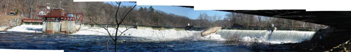
Figure One: Collins Hydroelectric Project. Panoramic view of dam taken from beneath the highway bridge.


            The original dam was a timber crib structure, built by the Collins Paper Company, in 1872. The dam spanned the Chicopee River and conveyed water, through a power canal, to waterwheels, located in the basement of the brick mill. As the timbers reached their useful life, the structure weakened. On March 7th, 1979, a freshet that peaked at 10,500 cfs, caused a catastrophic failure of the timbers and the dam breached.


            In 1982 Swift River Company, filed an ownership exemption, with the Federal Energy Regulatory Commission, to rebuild the dam and install a hydrogenation plant. The redevelopment scheme included abandoning both the power canal and the original timber crib dam design. The proposed project included a power plant, constructed integral with a Bascule style spillway. The former power canal was filled in. The river bed, downstream of the dam, was dredged to allow the head, at the exit of the old tailrace, to be brought upstream to the outlet of the new turbines. Two ESAC, 650 KW, pit bulb, turbines were installed in the powerhouse.


In plan view, the Collins Dam is a two section, dogleg. The primary length of the dog leg consists of a short Bascule gated section that extends from the north river bank, 56 feet to the powerhouse forebay wall, the powerhouse, and a much longer, twin, 64 feet long,  Bascule gated spillway that extends 128 feet to the abutment of the former power canal. The dam then swings 90 degrees and a lengthy canal spillway, runs parallel to the river’s edge, to the state highway bridge. Beyond this point, the former power canal has been completely filled in. The combined hydraulic capacities, of the fully depressed Bascule gates and the fixed canal spillway, with the headwater at the top of the abutments is 12,000 cfs.


In section, the dam has a rock filled base. The base is capped with heavily reinforced concrete. At 16 foot intervals, a heavy, steel, hinged, I-beam, needle, operated by a massive hydraulic cylinder, is attached to the concrete cap. The adjacent needles have southern yellow pine timbers stacked in their grooves. These timbers create movable panels that are raised up and down by the hydraulic cylinders. This allows the headwater elevation to remain constant with varying river flows. In between each four panel spillway is a robust concrete pier. Rubber seals are used to reduce leakage between the movable panels and the concrete piers. A heavy, steel, sheet pile, cutoff wall was driven 30 feet down into the river bottom upstream of the rock fill. The space between the top of the sheet piling and the rock fill was filled with air entrained concrete fill. Heavy riprap was placed on the downstream slope. A concrete pump was utilized to fill the interstices between the riprap with air entrained concrete. Automatic, unmanned operation was originally controlled by direct current, ice cube relays. These were replaced in 1989 with an Allen Bradley PLC (programmable logic controller). Fail safe operation was achieved by incorporating internal relief valves in the hydraulic manifold. In the event that the PLC and/or hydraulic system failed, during a flood, the relief valves are adjusted to open with a predetermined water surface elevation over the boards. The relief valve for each panel is set slightly higher then its successor panel. This allows the boards to fail in a controlled, progressive, cascade. Although this system was tested, it has never been used. The PLC, with its backup battery supply, has performed flawlessly. 


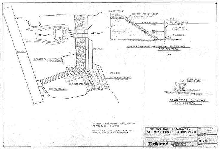
Figure Two: Plan View of Collins HEP Project.

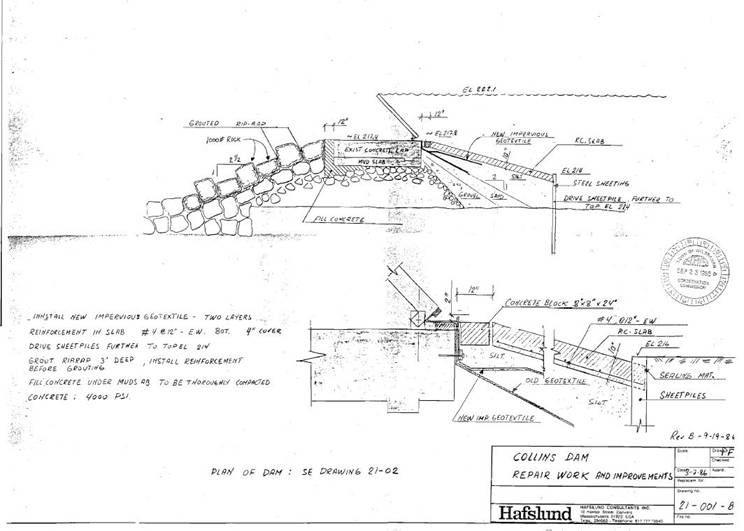
Figure Three: Sectional view of Collins HEP Spillway.


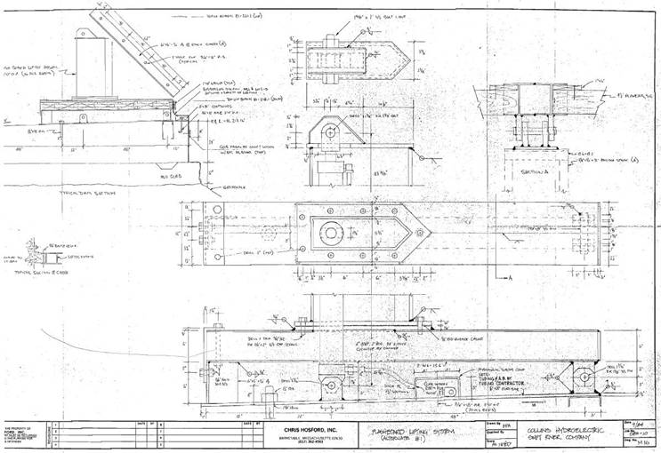
Figure Four: Detail drawing of Collins Bascule Gates

    The project was constructed in 1984. In the summer of 2006, after 33 years of continuous operation, the Bascule sections were rehabilitated. The old wood was removed, the needles were sandblasted and painted. The hinge pins were replaced. The hydraulic cylinders were rebuilt. The cylinders needed new seals, new cylinder tie rods and new pins. They were sandblasted and painted. The hydraulic lines were replaced with all new stainless steel lines. The hydraulic control manifold and hydraulic powerpack were replaced. An Allen Bradley, SLC 500 programmable logic controller was installed to replace the ice cube relay automatic pond, level, control loop. The cost of the rebuild was $ 260,000, including labor.


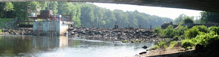
Figure Five: Summer of 2006 rehabilitation. Note all the wooden panels have been removed for replacement

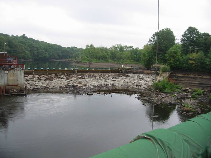
Figure Six: Summer of 2006 rehabilitation. Note all the wooden panels have been replaced. The blue barrels in the background are the boater safety buoys.

     In conclusion, the Collins Dam serves as a model for the proposed Lake Anastigunticook Dam Replacement. It is a simple, inexpensive structure. It has a moderate life span. The life span can be easily prolonged with simple maintenance. It has flawlessly functioned for 33 years. 

 The construction of a Collins type dam, at the proposed dam site, at Lake Anastigunticock is simplified. This is because the leveling slab can be poured directly on the underlying ledge. This eliminates the rock filled section. The use of a PLC based control system allows the lake level to remain constant. This is achieved by lowering the timber panels with the hydraulic system as flood flows increase. Once the panels are fully depressed, the hydraulic profile reverts to channel control exerted by the historic channel walls. The hydraulic system is charged with water soluble, environmentally friendly oil.

 The following photographs depict the summer of 2006 rehabilitation:

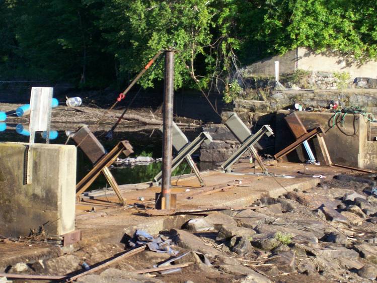
Figure Seven: Hydraulically controlled,  I-Beam, Needles. Note the rectangular caps that the cylinders thrust on. The caps allow the boards to fully depress. They also protect the cylinder from debris flowing over the dam crest.


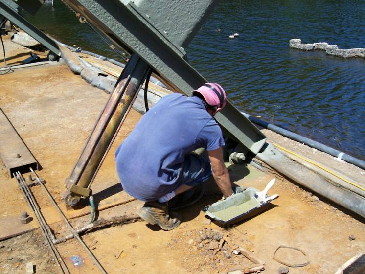
Figure Eight: A close up view of a hydraulically controlled,  I-Beam, Needles.


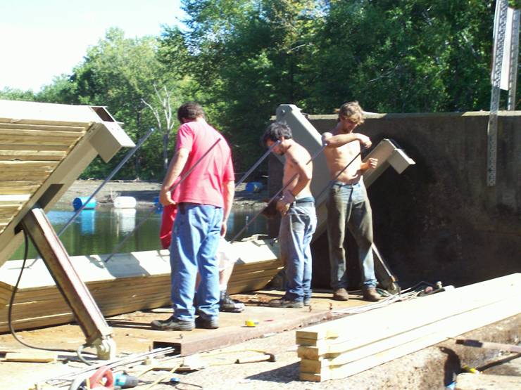
Figure Nine: Note the laminated panels being held together with stainless steel, threaded rod. This is a simple, durable method of construction

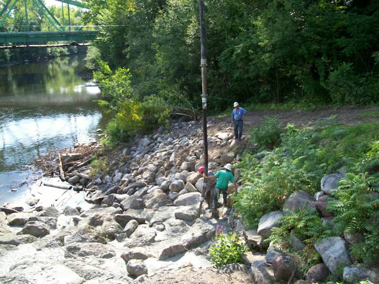
Figure Ten: The downstream riprap being stabilized with air entrained concrete.Up lift on the finished riprap was prevented with subsurface drains.