French River's
Mission
French River Land
Company
(FRL) develops small and micro hydro
resources. As hydro developer, French River provides
the unique experience, engineering and
craftsmanship to build and operate hydro projects in the
Northeast.
FRL was
incorporated on February 10, 1992. Since 1992, French River has
owned the dormant South Village hydro project. In June of
1997 FRL purchased the Tannery Pond Hydro Project in Winchendon,
MA. It went on line in June of 1999 to satisfy FERC license
requirements. Due to contract negotiation problems, with
Templeton Power & Light, it did not commence commercial
operations until May of 2004. At that time, Will & Celeste
negotiated a new power sales contract, with with the
Massachusetts Electric Company. They received their first check
from the Massachusetts Electric Company in June of 2004! This
was the first cash flow the site had earned in over 50
years!! (see the Tannery Pond sidebar) In December of 2003,
Celeste and Will Fay purchased the entire stock of FRL. In March
of 2004, FRL purchased Golden Pond Hydro in Ashland, N.H. This
site was last operated in June of 2002 when it was badly damaged
by a lightening strike. On January 3rd of 2008, Golden Pond
Hydro began commercial operations with a signed contract with
the Ashland Electric Light Department. It took almost four
years, of weekends, to rebuild the badly damaged and thoroughly
worn out tube turbine (see the Hydrolec disassembly, Hydrolec
Rebuild and Golden Pond Hydro sidebars).
Celeste N. Fay is
the President of FRL and her brother,
William D.B.
Fay is the Vice President. Celeste and Will
are
recent graduates of WPI with BS Degrees in Civil Engineering.
Celeste and Will have several years of
power plant, O and M experience with D. Hobbs Contracting and
Swift River Hydro Operations Company and have worked extensively
with their father. FRL has the tools, equipment and shop
facilities to fabricate and repair hydroelectric equipment,
regardless of its age or design.
William K. Fay
P.E., FRL's
Chief Engineer and General Manager, is
a licensed hydro engineer who has inspected 80 dams for
the Massachusetts Dam Safety Division and is authorized by the
Federal Energy Regulatory Commission (FERC) to perform Part 12
inspections of licensed hydropower facilities. He and his
children, Celeste and Will, have rebuilt many small hydro plants
located throughout New England.
_________________________________________________________________________________________________
_________________________________________________________________________________________________
March 28th,
2013
We had a
babbitt radial bearing that needed to be repoured. In addition
the intermediate shaft where the bearing journal is located
needed to be refinished. We received a quote of $7000 to pour
and machine the bearing. We decided to do it ourselves. Here is
how we did it:
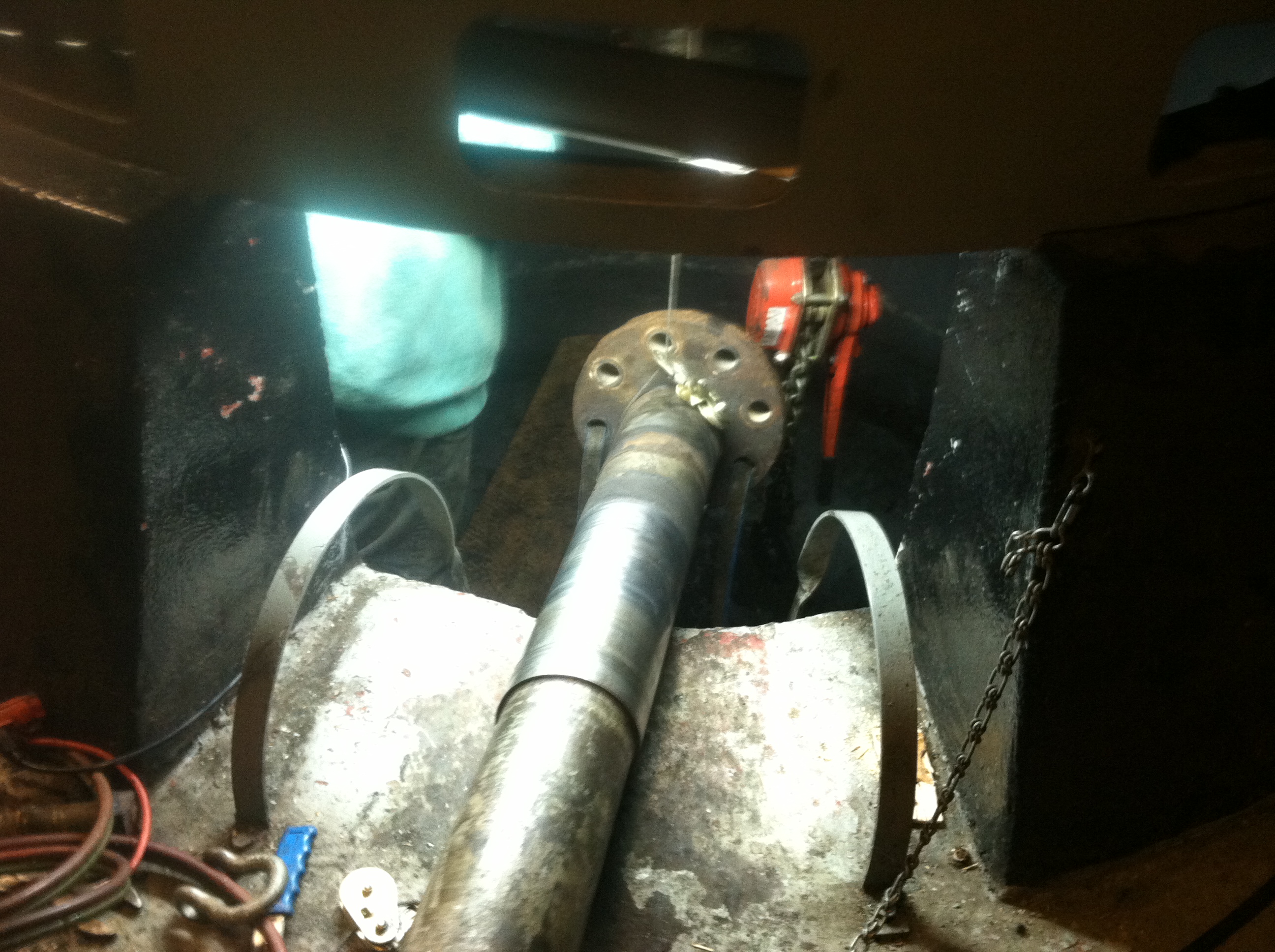
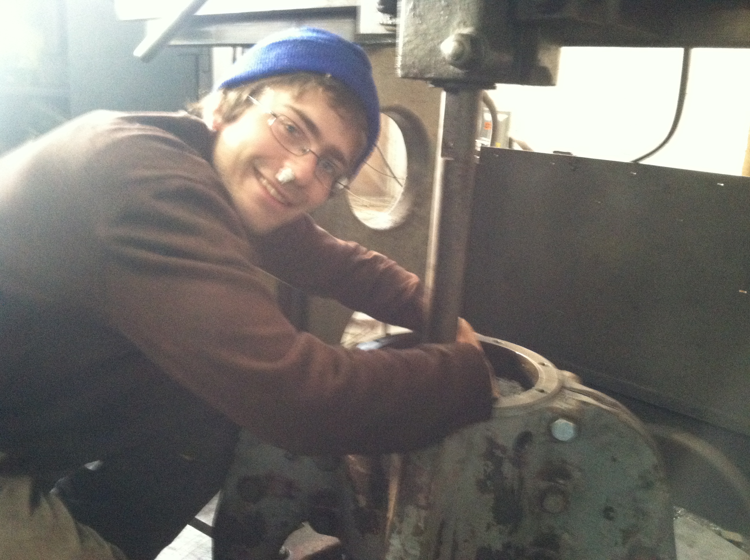
Will has
detached the main shaft. We have rigged it out of the pit. The
half coupling on the end of the shaft is attached to the top of
the runner with 1 1/2 inch studs and nuts. The shiny surface is
the scoured bearing journal.
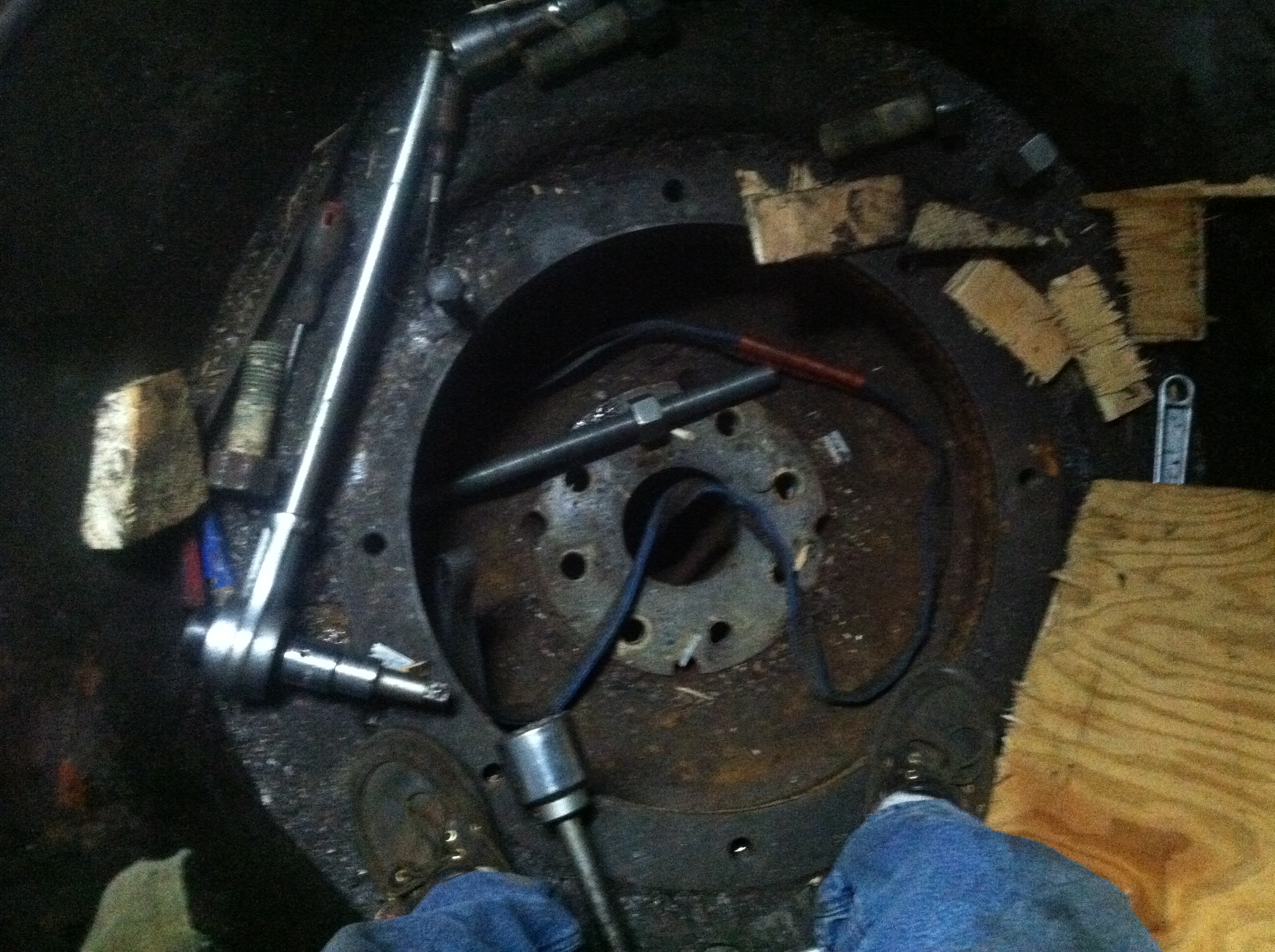
You are looking down at the
top of the Francis runner. My foot is resting on the flange
where the stuffing box is bolted down. The runner has not
dropped into the draft tube because Leffel turbines incorporate
a step in the bed ring that prevents the runner from dropping.
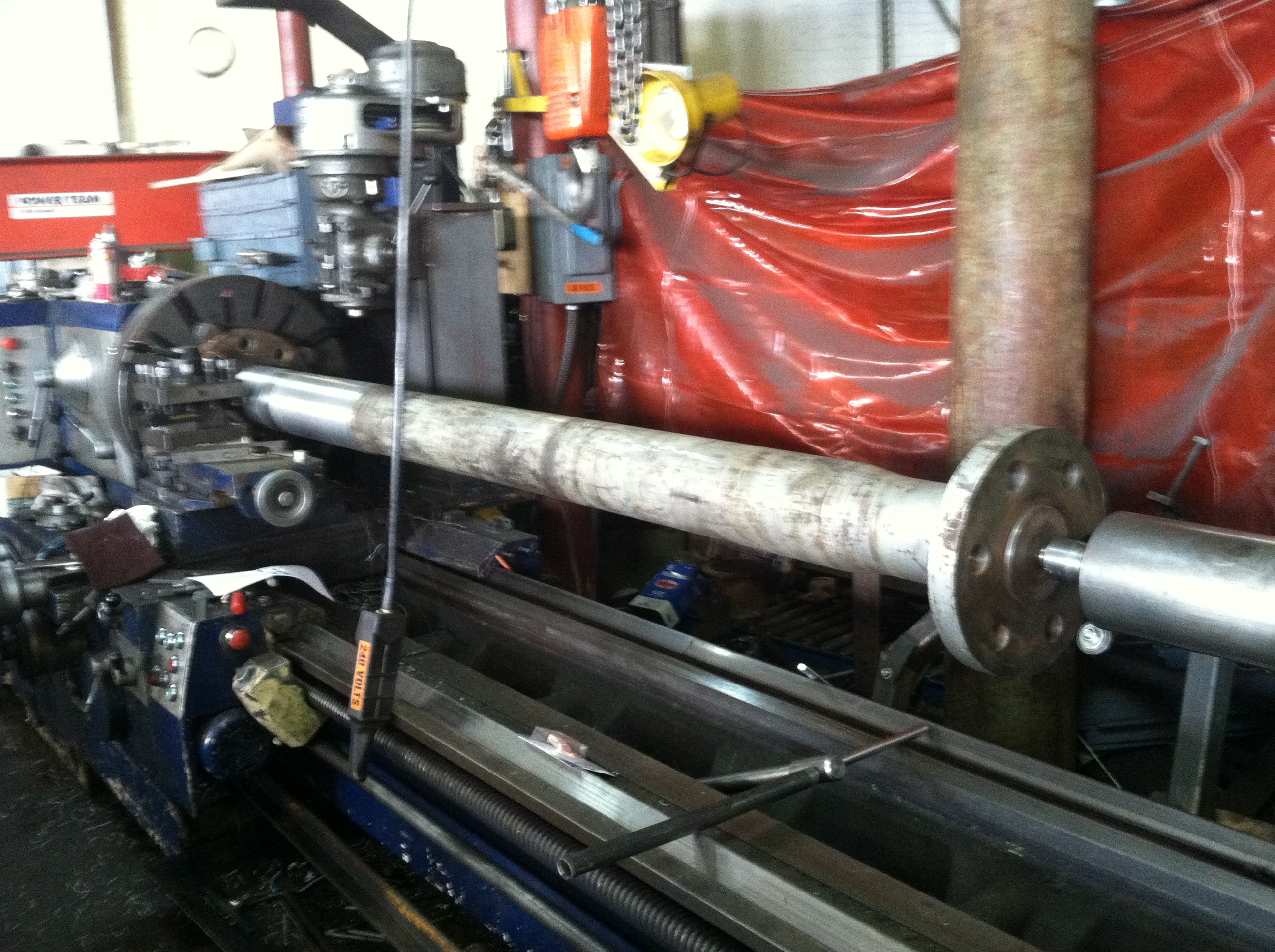
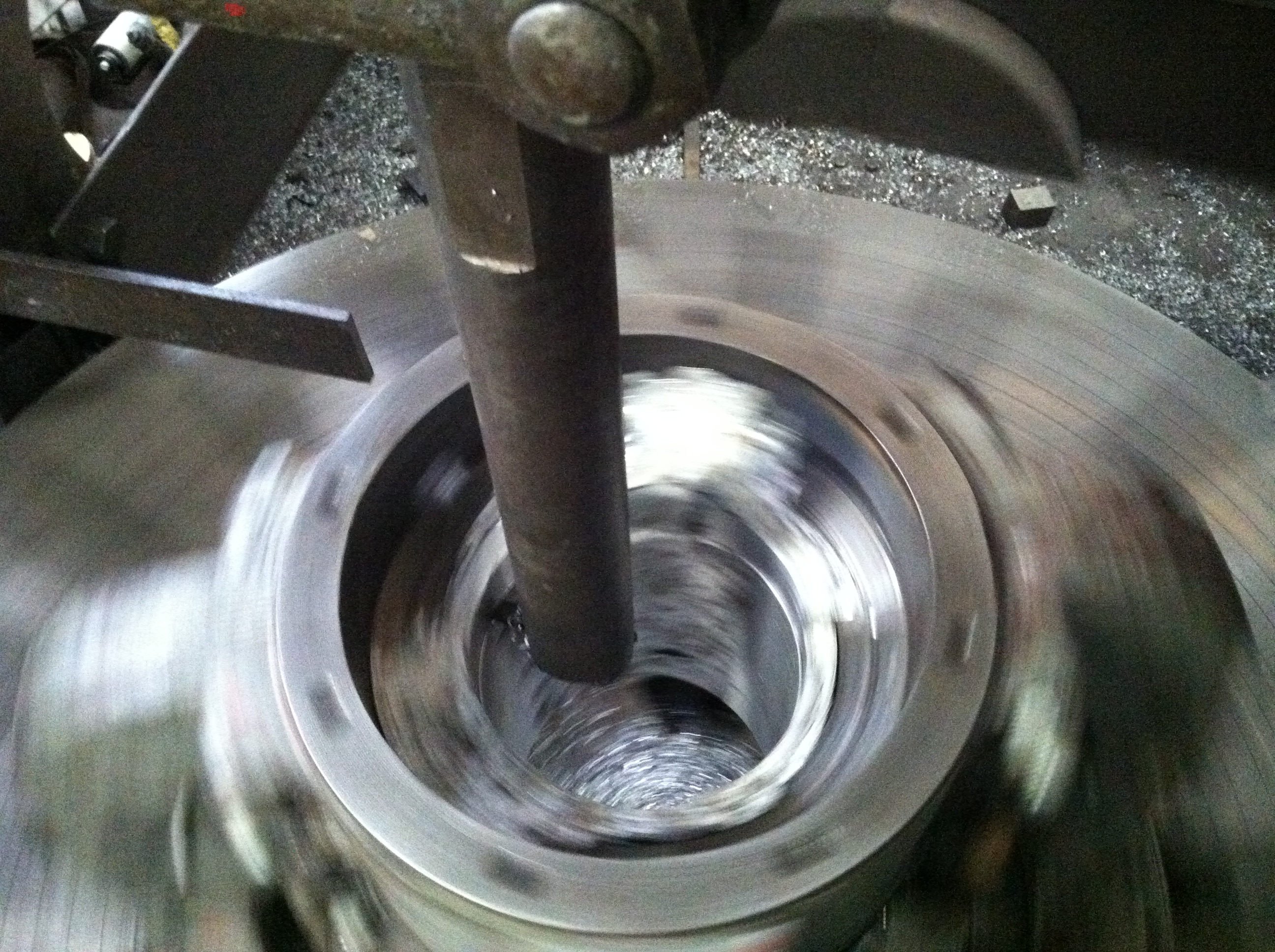
Will has installed the
turbine main shaft into our Poreba roll lathe. The center hole
on the generator end was not exposed to water and was still
usable. He indicated the turbine end in the four jaw chuck.
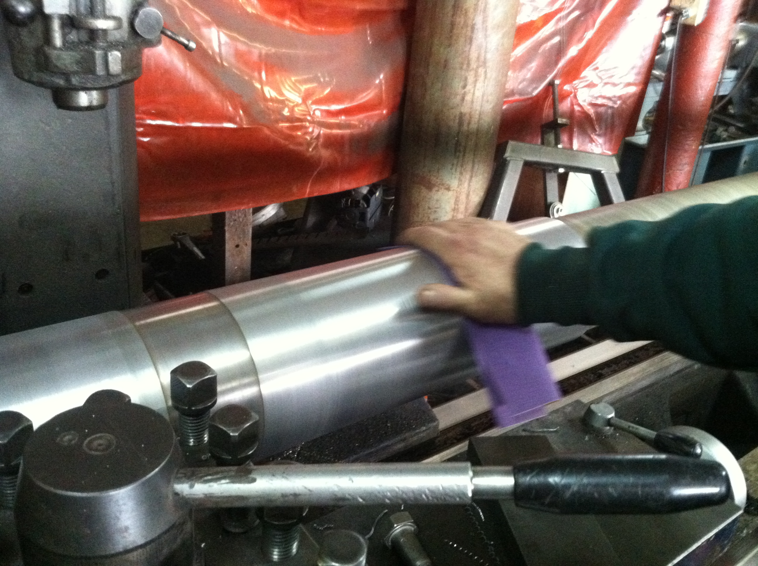
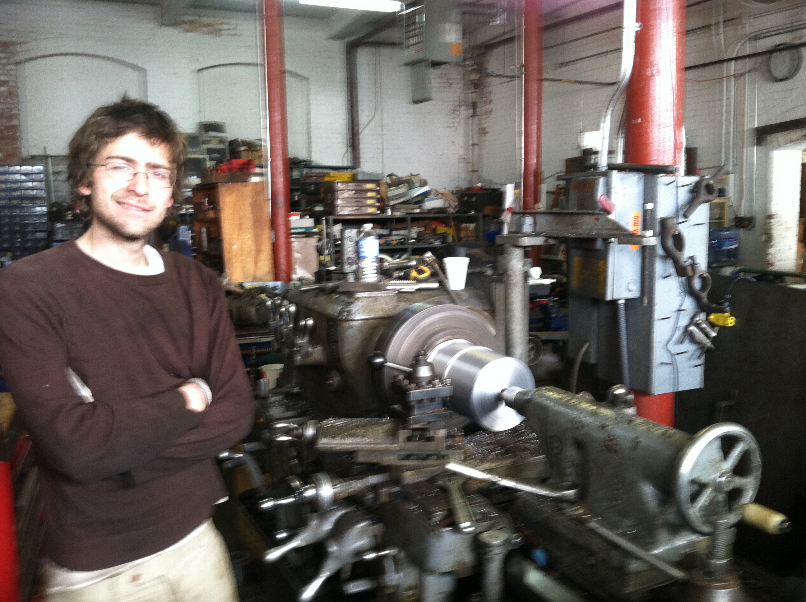
Here, Will is polishing the
finished journal prior to removing the main shaft from the
lathe.
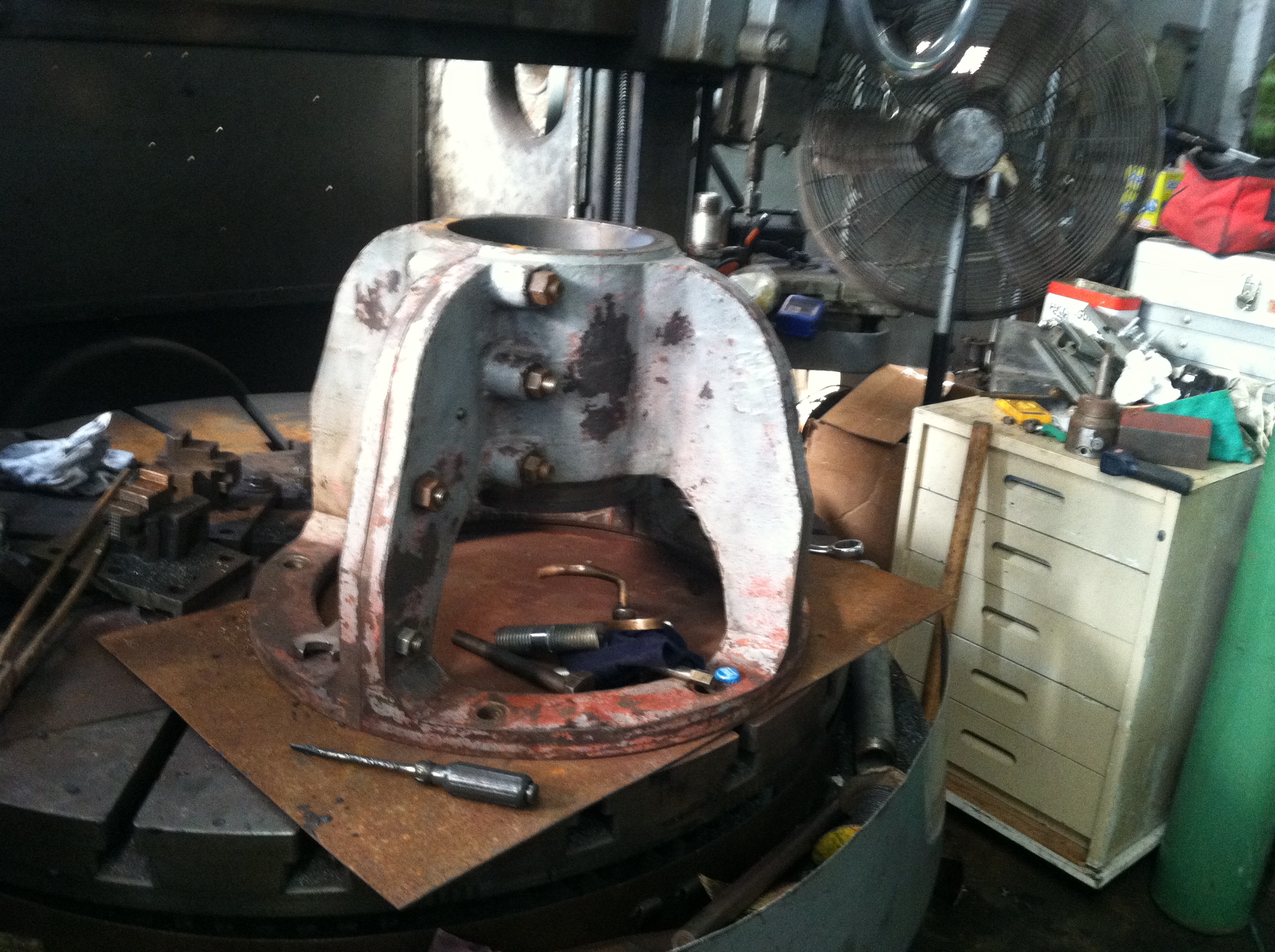
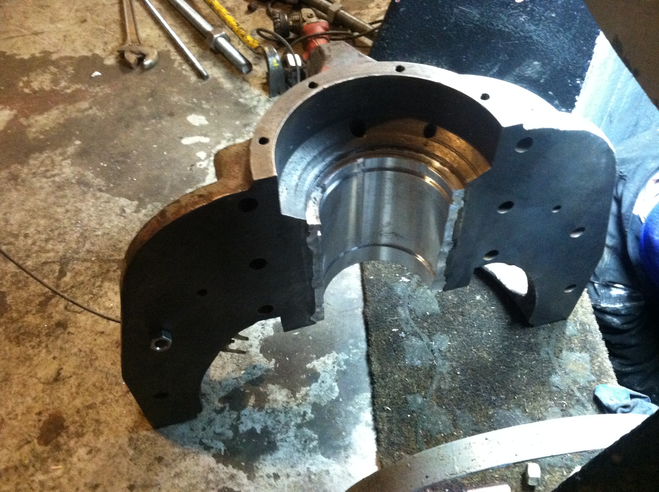
Here is the
radial bearing prior to melting the old babbitt out of the cast
iron housing.
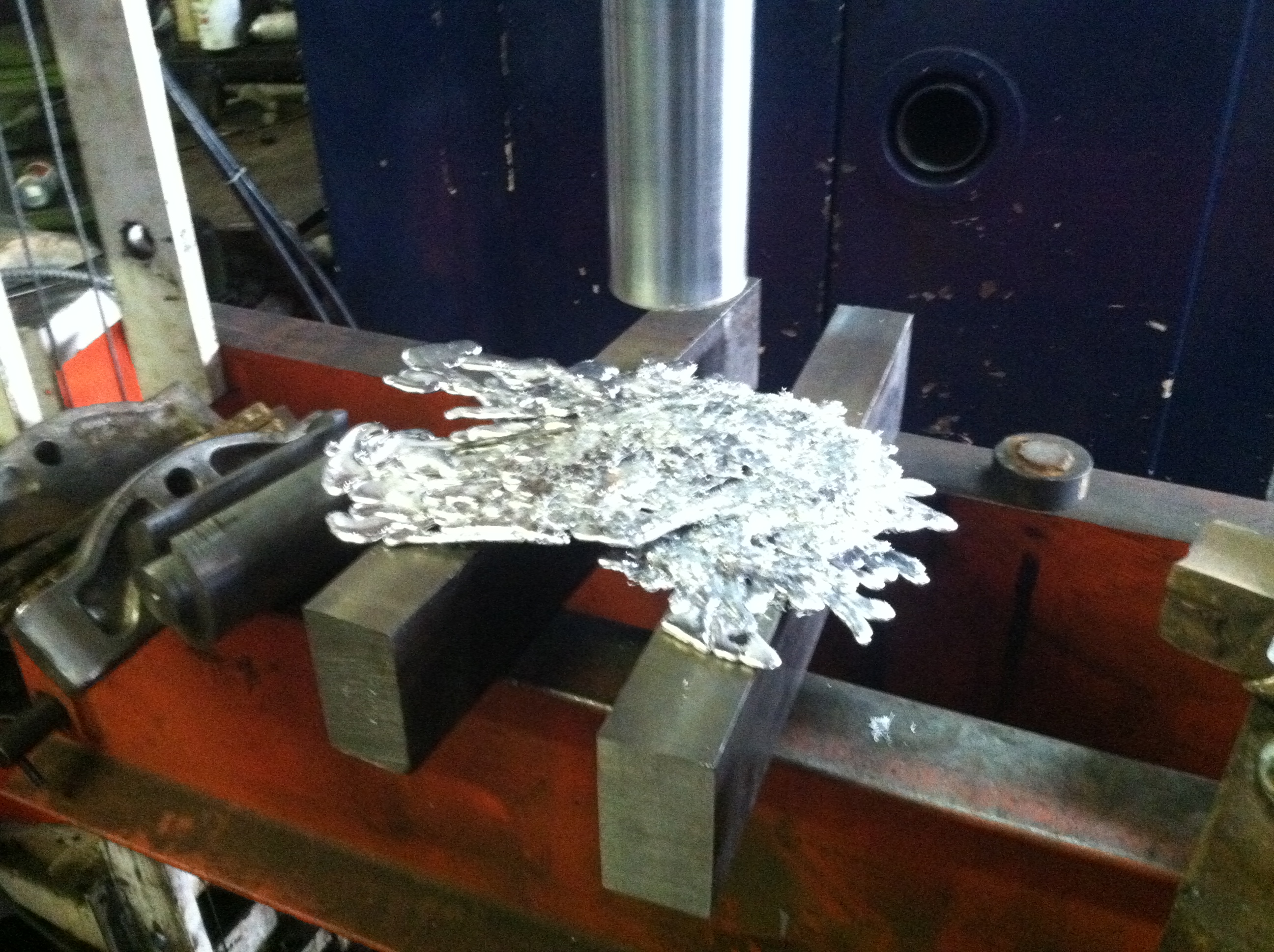
Here is some of the babbitt
that I melted from the bearing. Previously we scrapped out a GE
motor and I kept the bearing journals for their babbitt. Notice
the snow white color of the Leffel babbitt. When I subsequently
melted the babbitt from the GE bearings it was a beautiful
golden color. We melted the two babbitt metals together in a
ladle and thoroughly mixed the metals.
In order to pour the molten
babbitt into the bearing, we took a chunk of old shafting and
turned it down. For most of its length we turned it 1/4 inch
less than the main shaft diameter. We stepped it up to the
inside diameter of the the housing bore, for about 3/4 inch. We
than stepped it up to the original diameter of the round stock.
Will is turning the faux
turbine shaft that will be clamped in the cast iron bearing
housing.
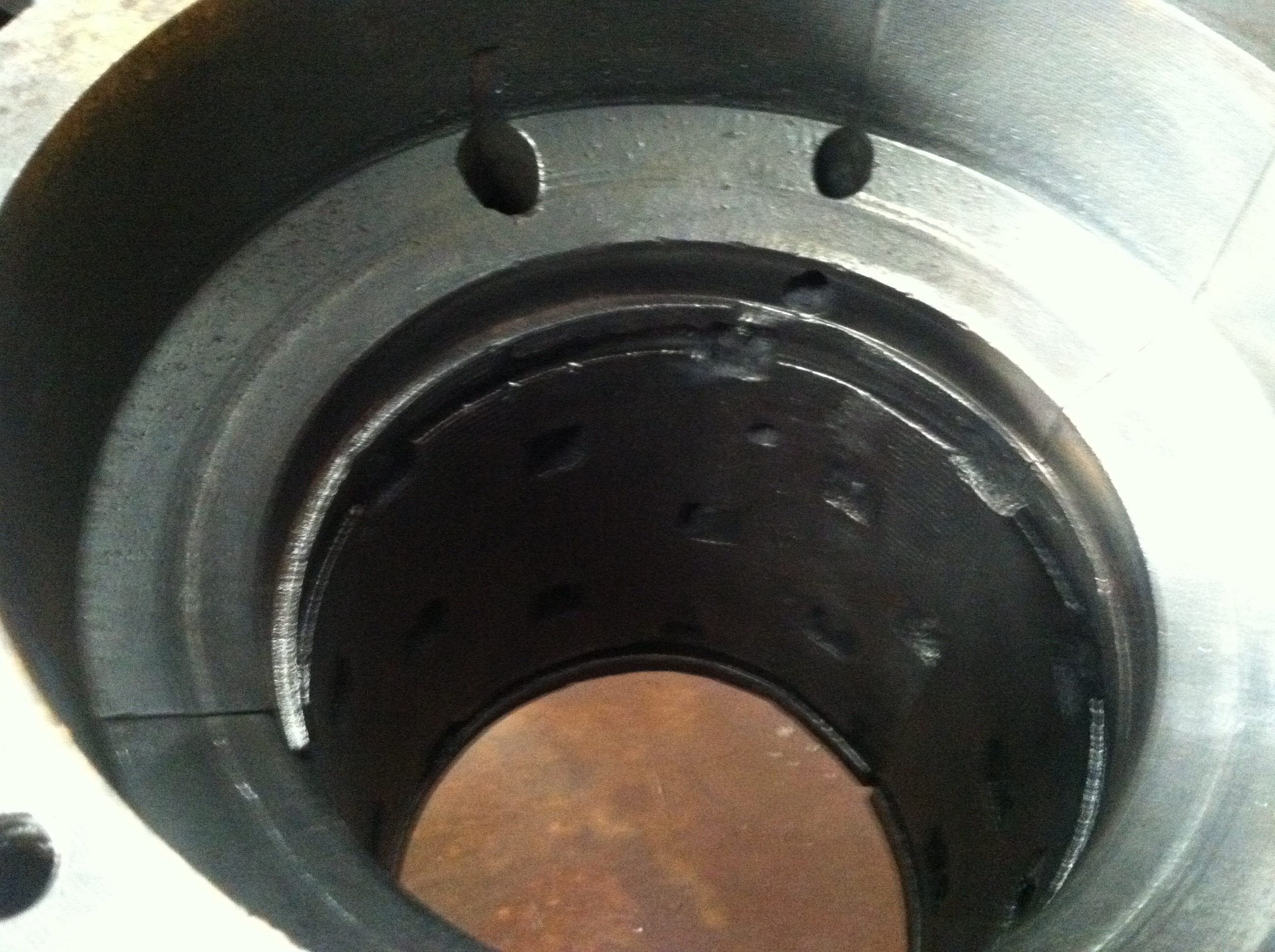
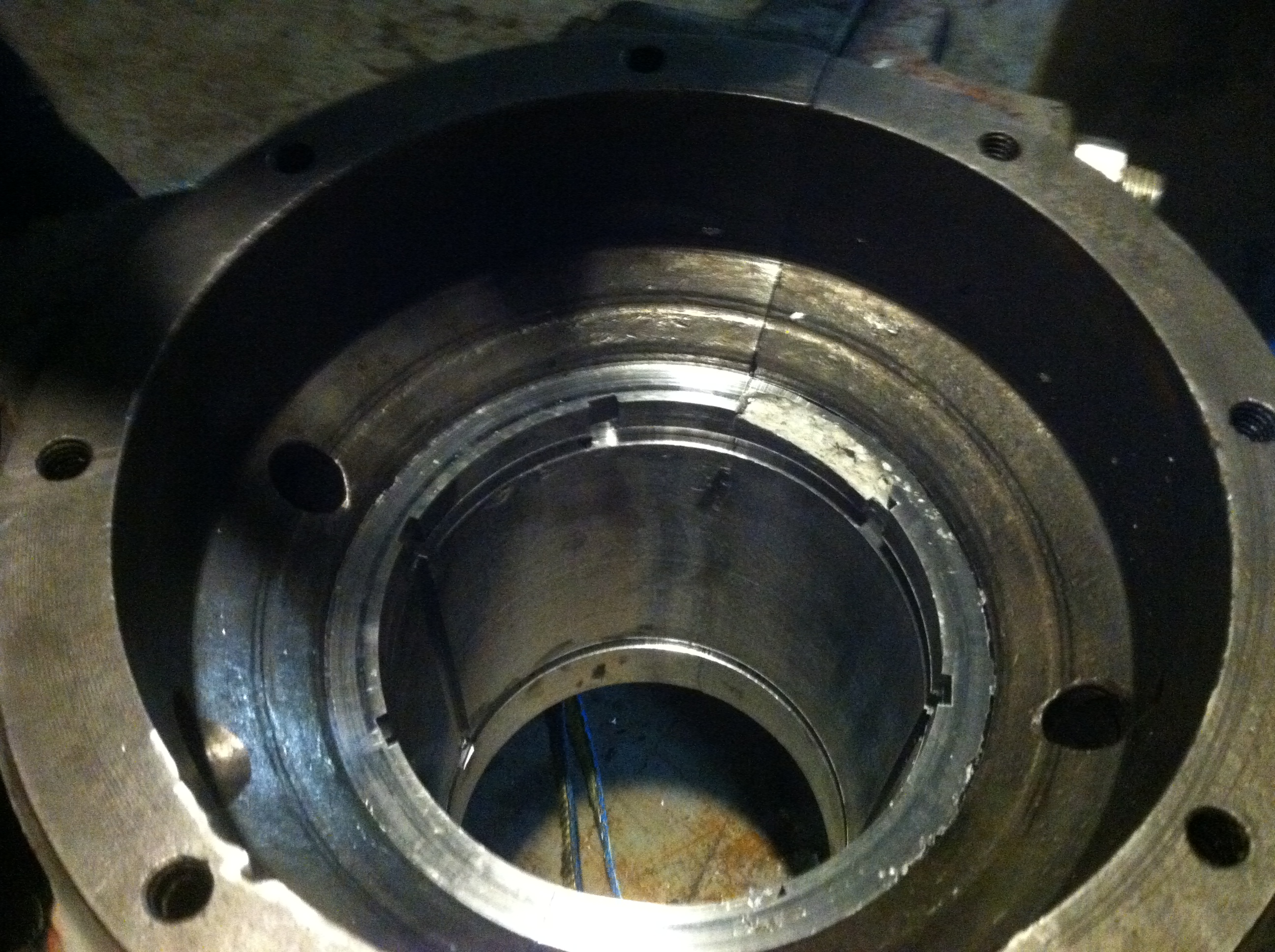
This is a
view down the bearing bore of the cast iron housing after I had
melted out the bearing. Note the square holes in the surface of
the bore used to mechanically lock the babbitt in place. I wire
wheel brushed the bore and decontaminated it with electric
contact cleaned prior to pouring the molten metal.
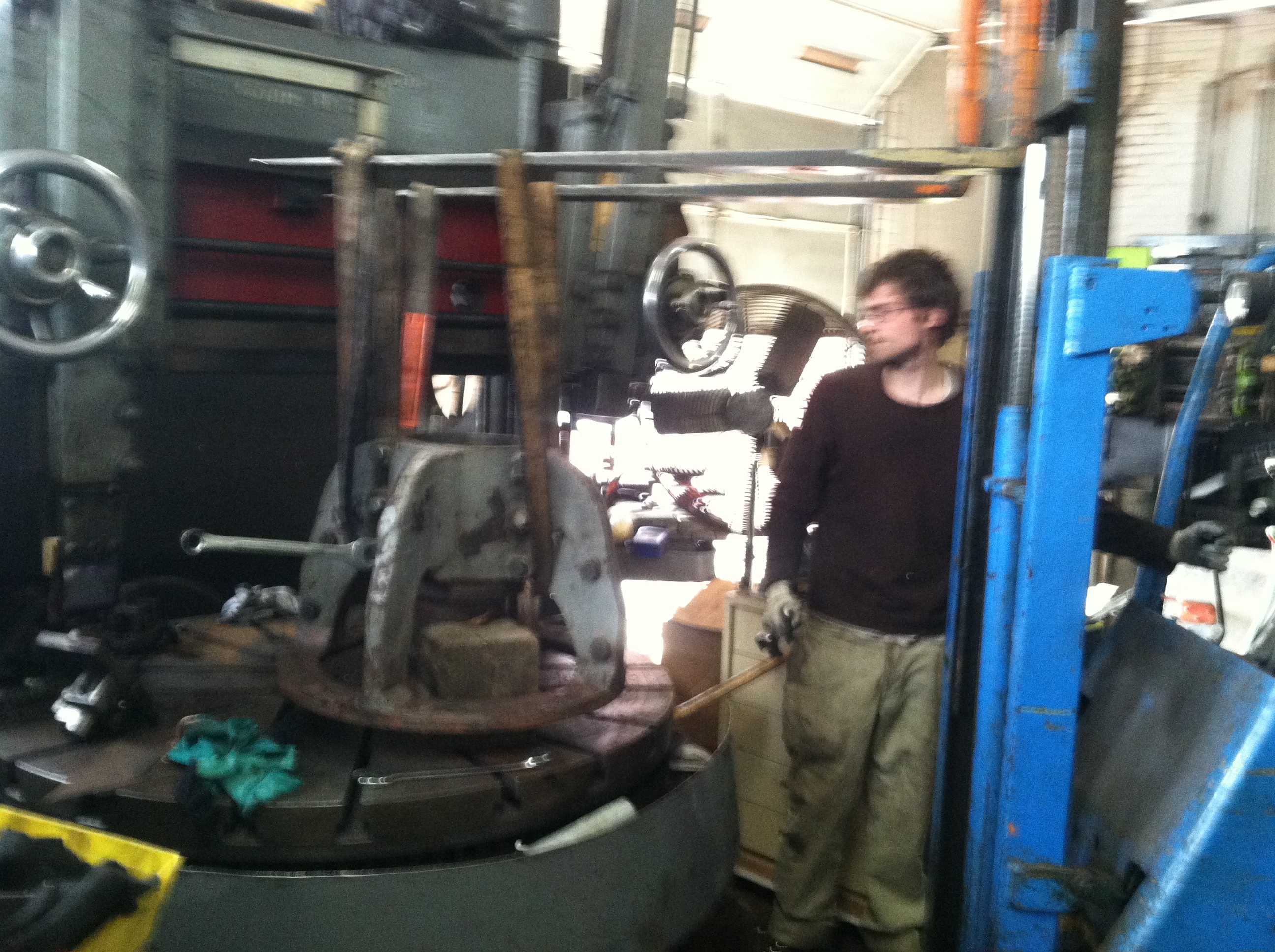
Will is using the forklift
truck to lower the assembled and sanitized bearing housing onto
the faux shaft. Just prior to this he lit the oxyacetylene torch
with just the acetylene jet. He used the heavy carbon smoke to
coat the faux shaft to prevent the babbitt from sticking to the
shaft.
Here is the faux shaft
bolted in place for sizing. We added aluminium flashing
separators. The separators were clamped between the bearing
halves and extended to the faux shaft. These were added so that
after the molten babbitt cooled, we could separate the two
halves of the split bearing.
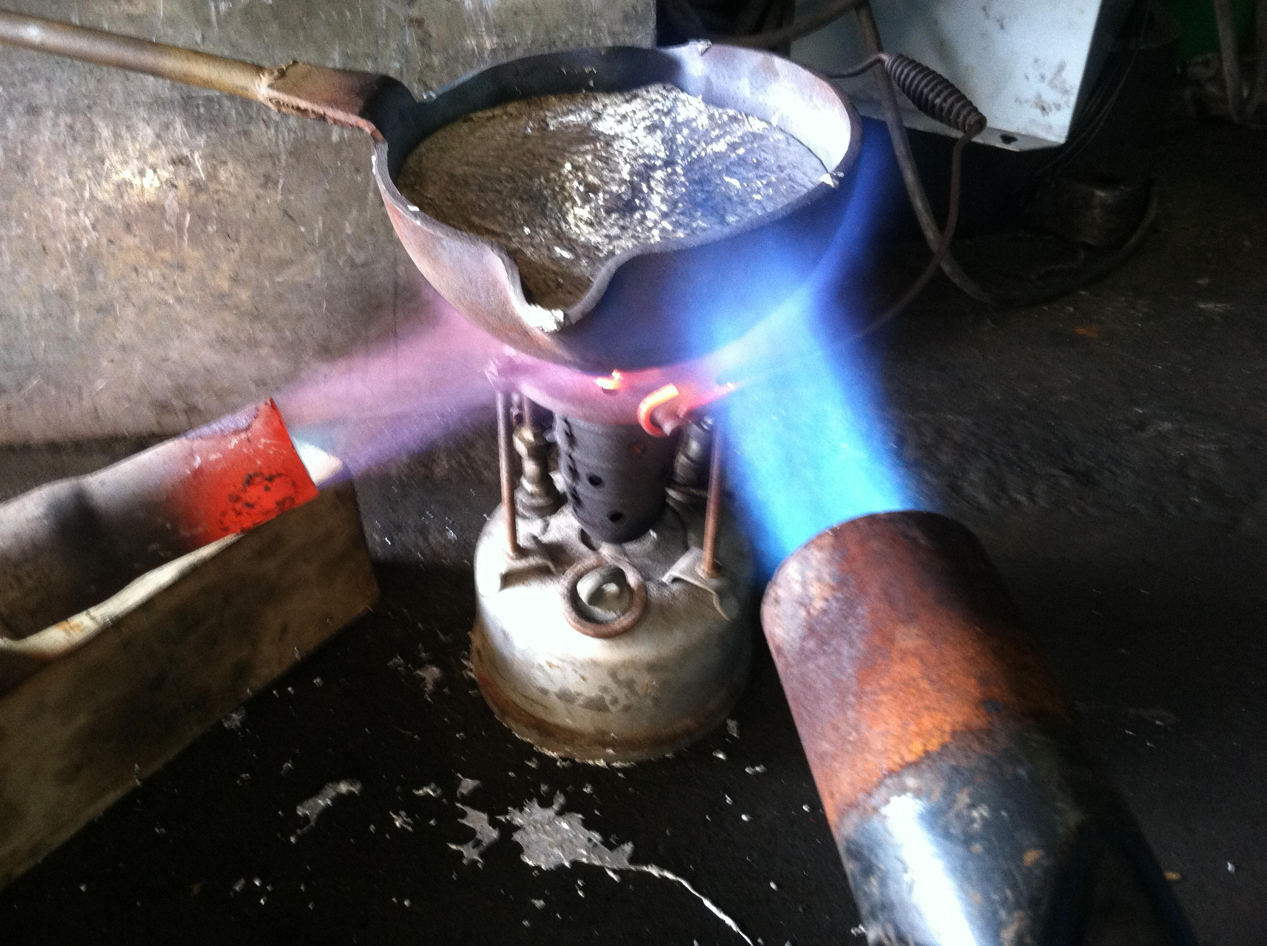
We used a
babbitt pot and two propane berthas connected to barbecue grill
tanks to melt the babbitt. We are using a foundry ladle to hold
the molten metal.
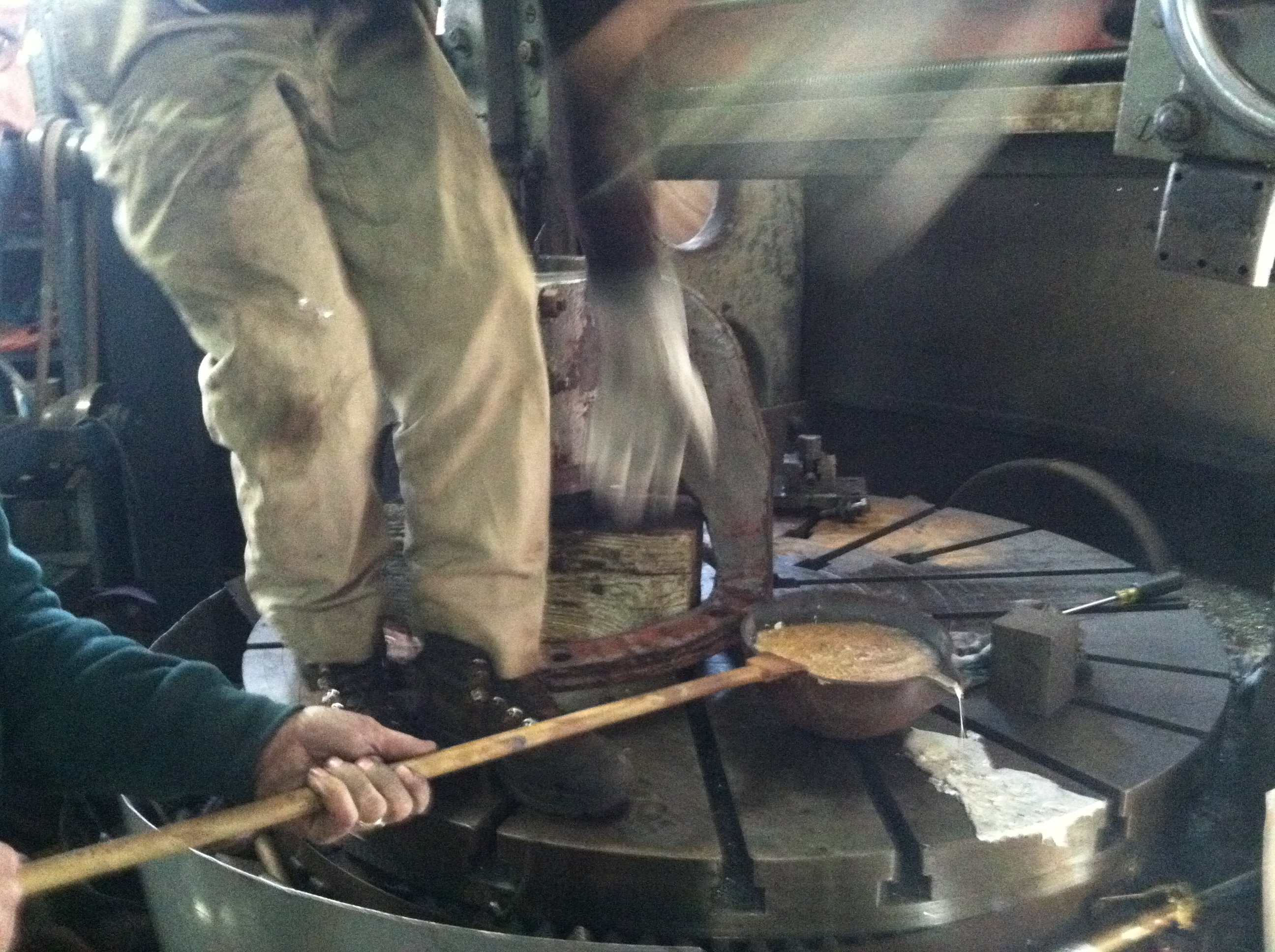
We are passing the ladle to
Will.

Warren is supervising the
pouring of the molten babbitt into the bearing housing. Note the
aluminium flashing used to separate the two sides of the
bearing.
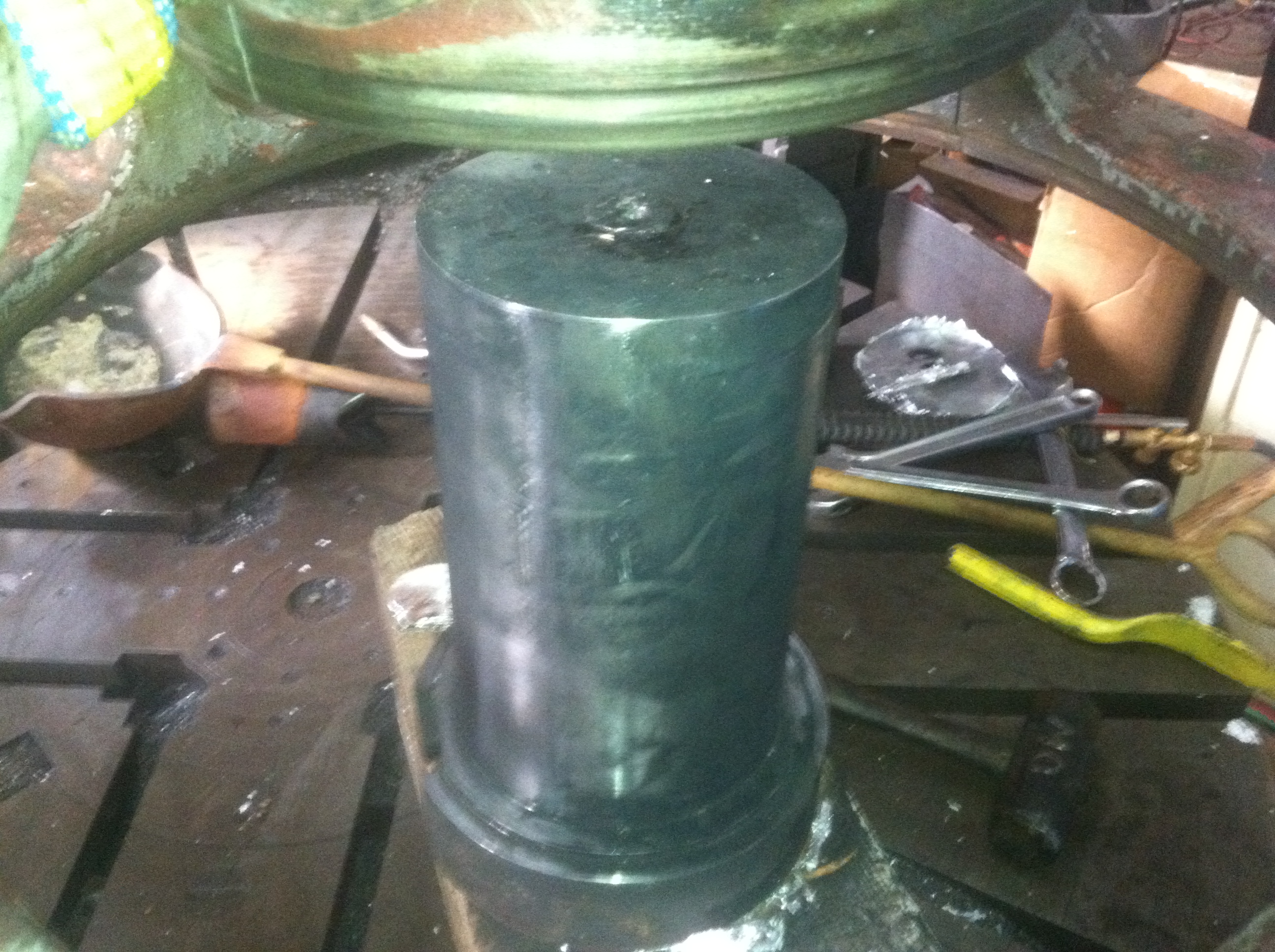
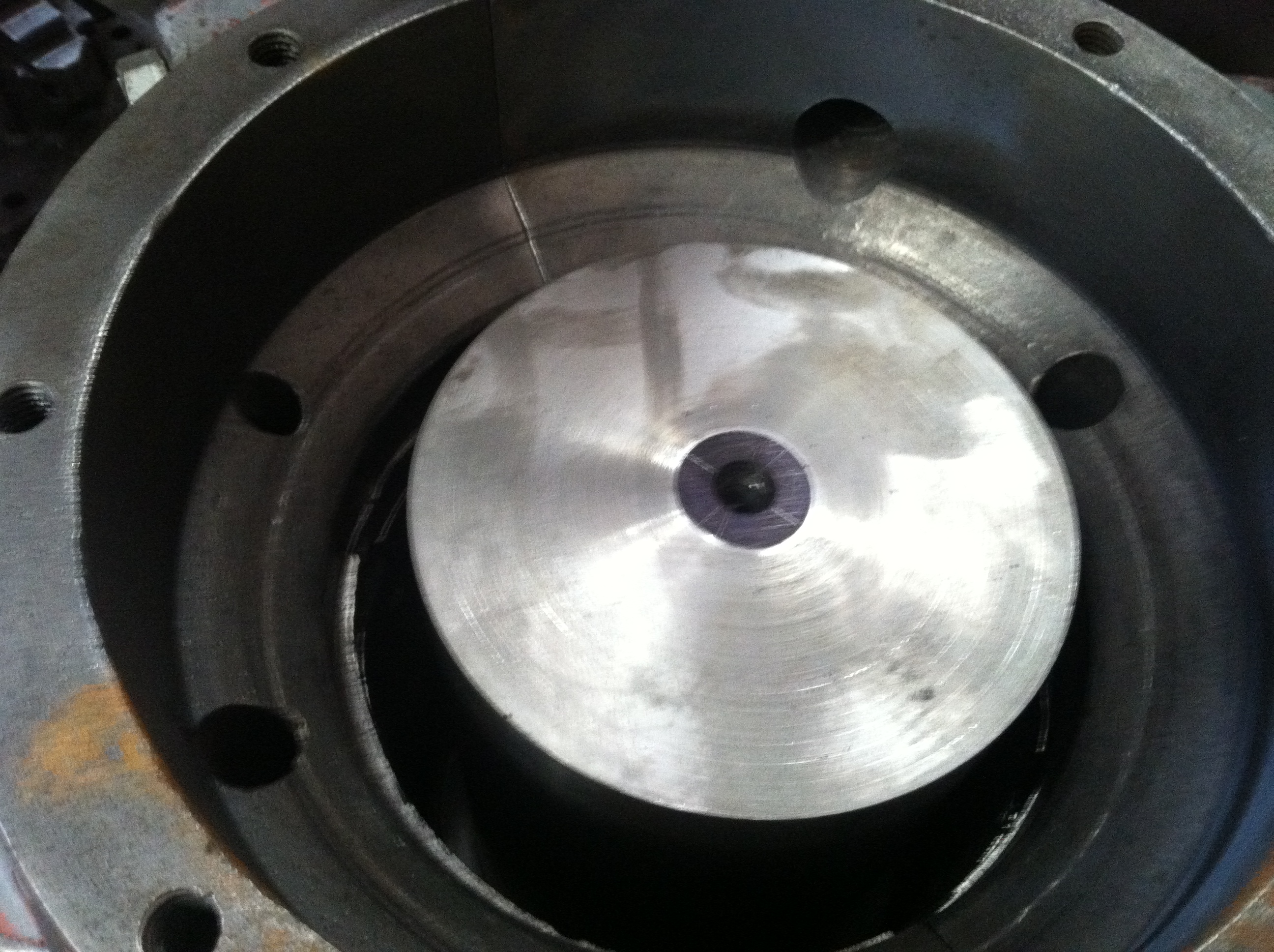
This is the next morning.
The carbonized faux shaft has been extracted from the newly
babbitted bore.
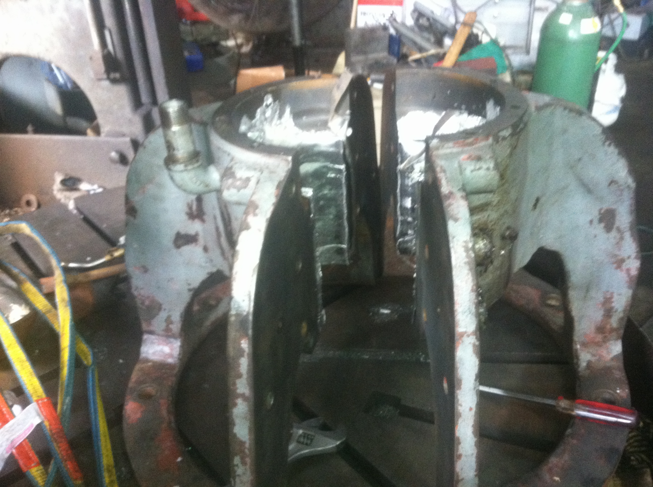
Will has successfully split
the housing in half.
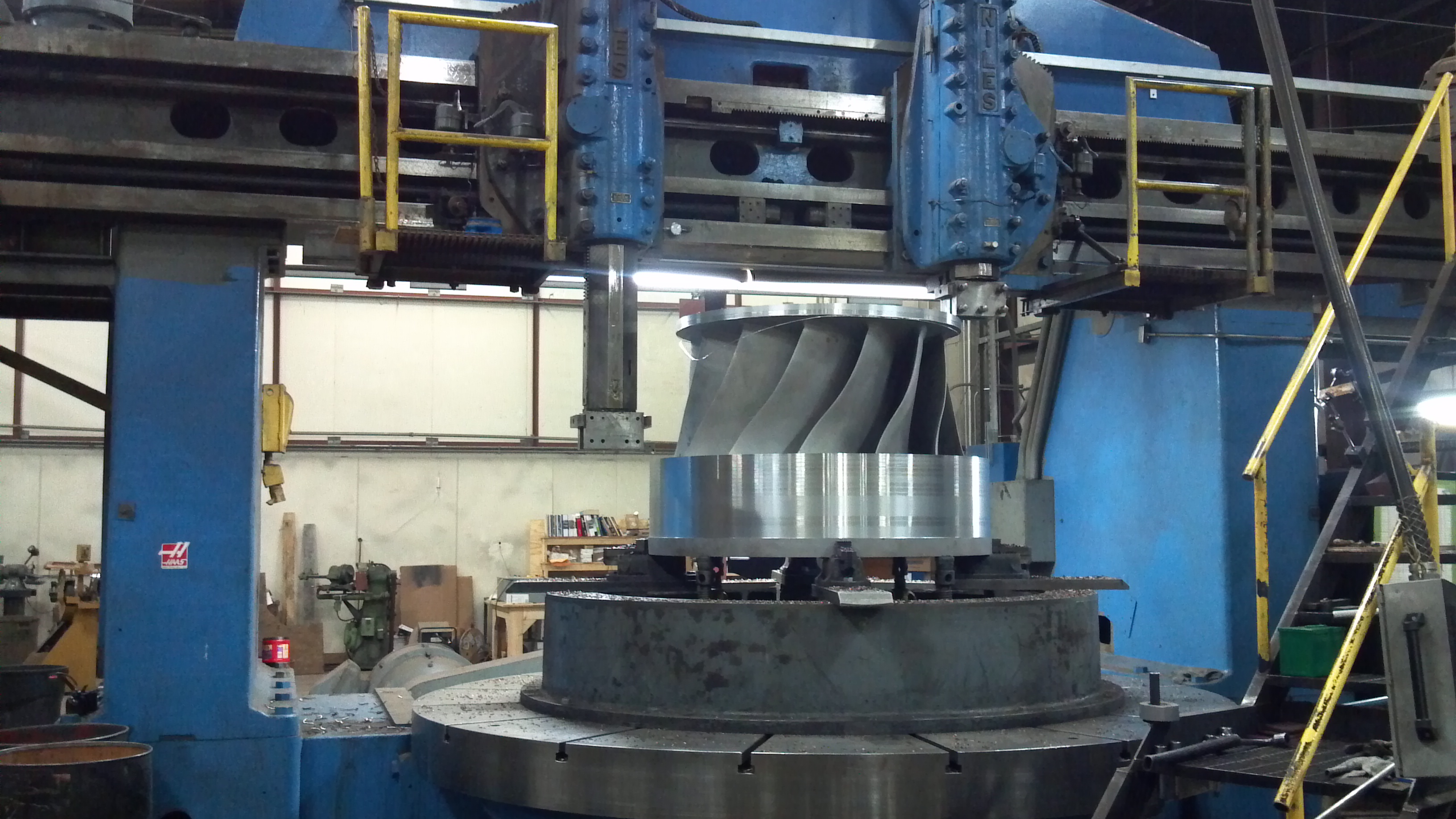
Will is checking the bore
diameter after taking a pass with the Bullard vertical turret
lathe.
Looking down the babbitted
bearing bore while it is being turned with a carbide single
point tool.
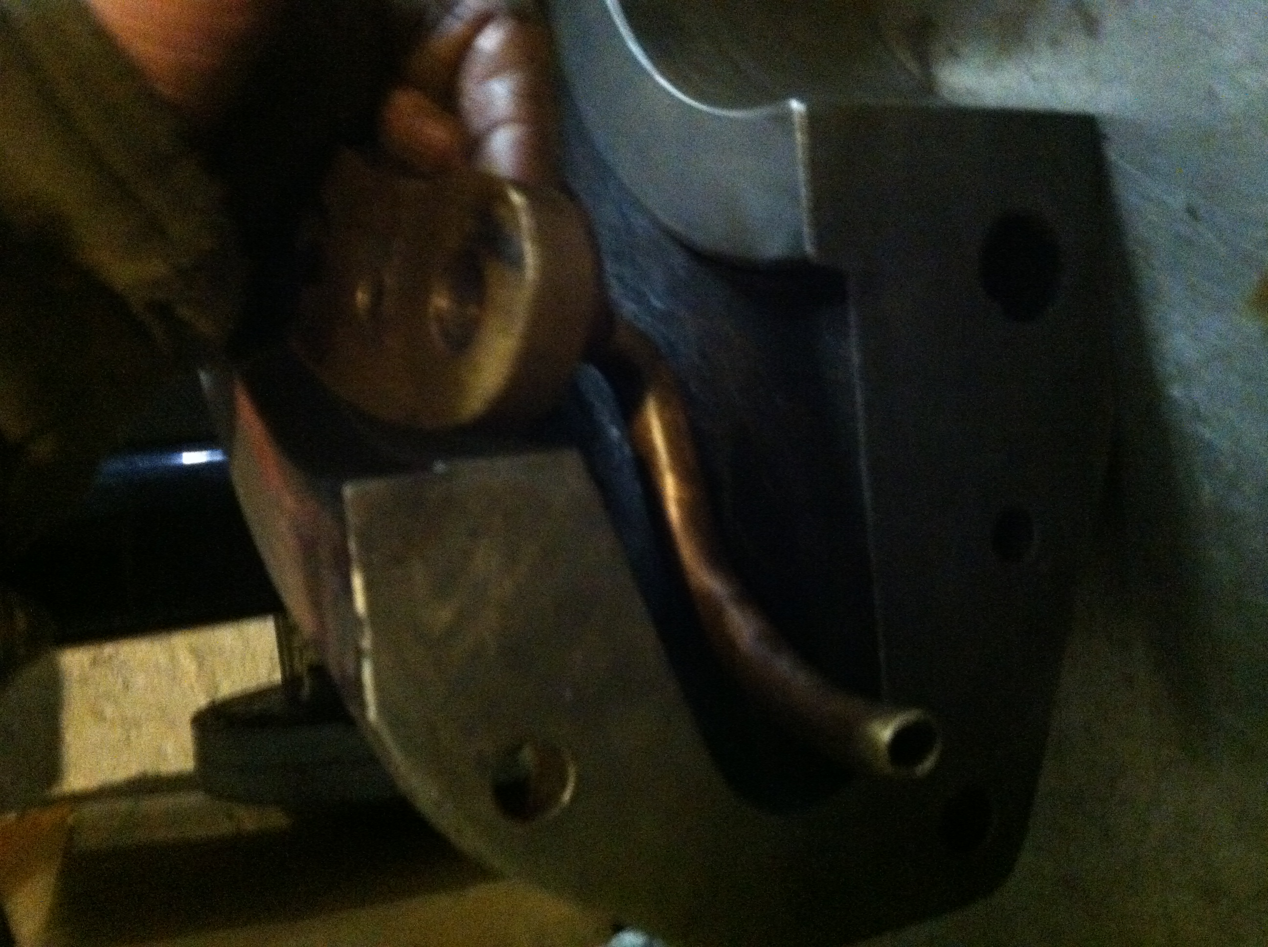
Here is the finished
bearing. Note the horizontal and vertical grooves machined into
the surface of the babbitt. They are used to distribute the oil
around the turning shaft. Note the two vertical holes drilled
into the bearing housing on ether side. This bearing has an
unusual pumping system. The bearing housing is stationary.
Beneath the bearing housing is a cast iron bowl that mounts to
the shaft and rotates with it. The bowl is filled with oil. A
precisely bent brass tube is attached to the bottom of one hole.
Its other end points into the oil. As the shaft rotates the oil
and bowl, the oil is forced into the tube and is pushed to the
top of the bearing. The oil spreads out and drops into the
clearance between the shaft and the beating. The excess oil
drops back into the bowl through the diametrically opposite
hole.
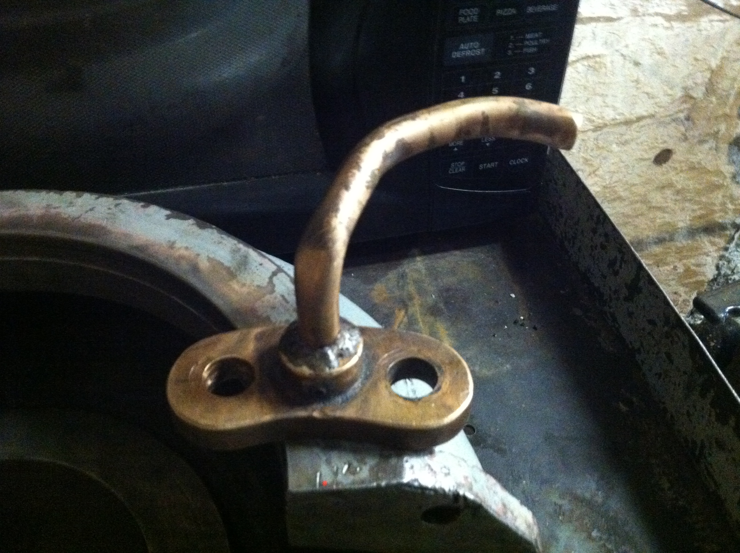
This is the bent piece of
brass pipe that forms the entrance to the pump. It is resting on
one half on the split bowl.
I am demonstrating how the
pump pipe is installed and how it works.
Another view of the
finished bearing prior to rigging it into the hole.
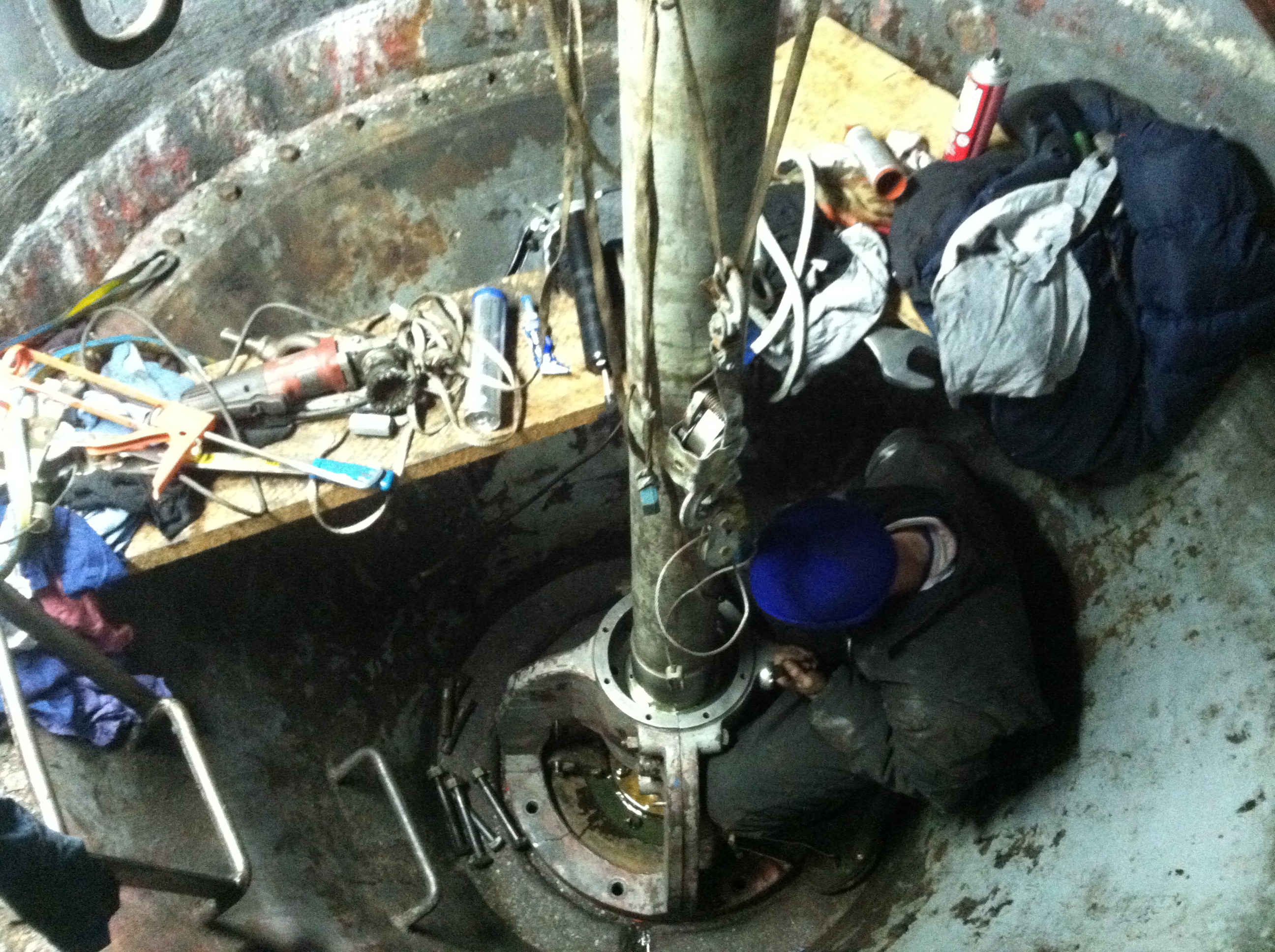
Will has re-installed the
main shaft. It has been bolted to both the generator shaft and
to the top of the runner. He has rigged the two halves of the
bearing housing into the pit. He coated the bearing journal with
blueing compound and turned the generator shaft. He re-split the
bearing and scraped the high spot off of the babbitt bearing
surface with a bearing scraper. He has now re-assembled the
bearing. Note the bronze stuffing gland beneath the bearing. The
rotating oil bowl has not been installed at this time.
January 23,
2013
Our brand
new, Kiser turbine arrived yesterday.
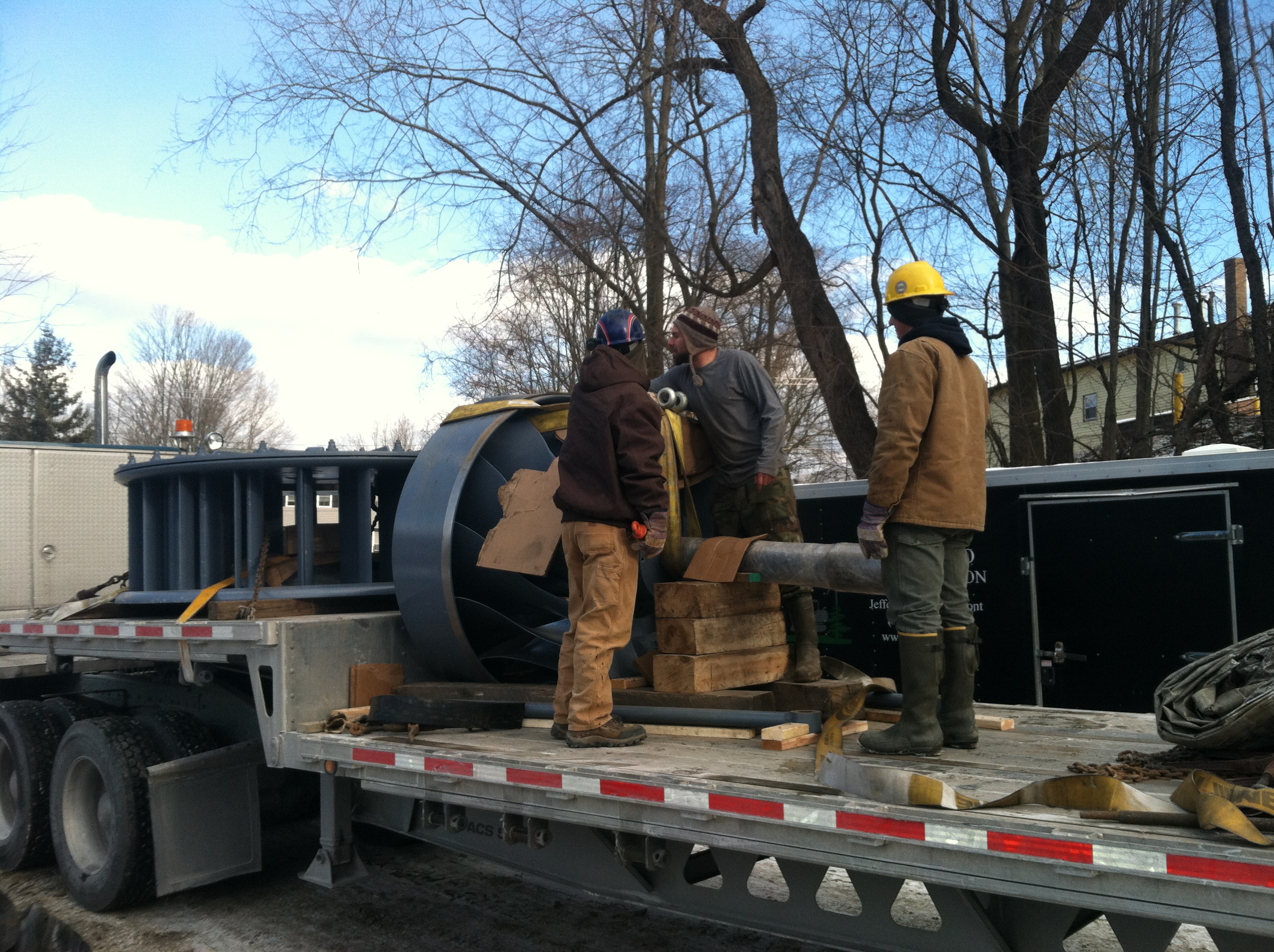
Here, the guys have uncovered
the gatecase and runner. They have inserted a 30 ton strap
through the blades in preparation for the excavator to unload
it.
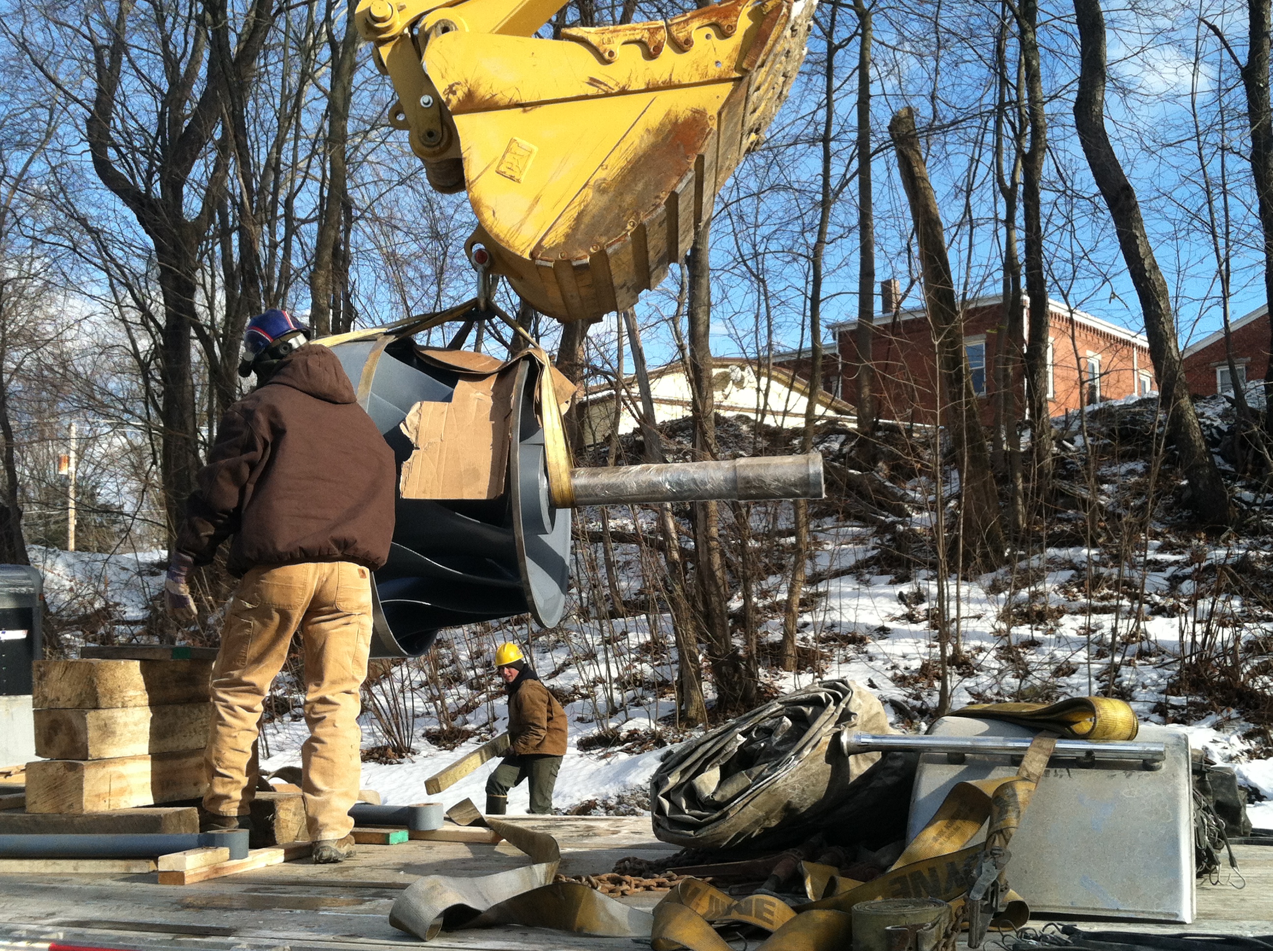
Here, the new runner is
hanging by a single large shackle from the excavator.
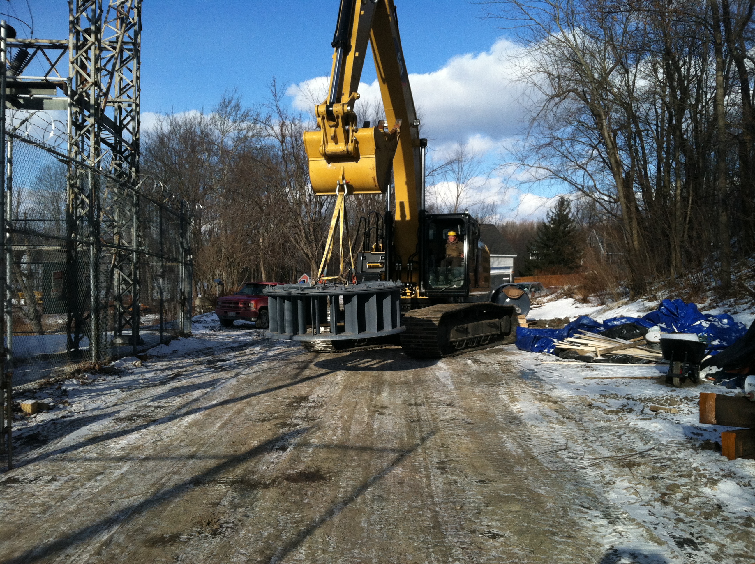
We are transporting the new
gate case to the lockup at the transformer yard.
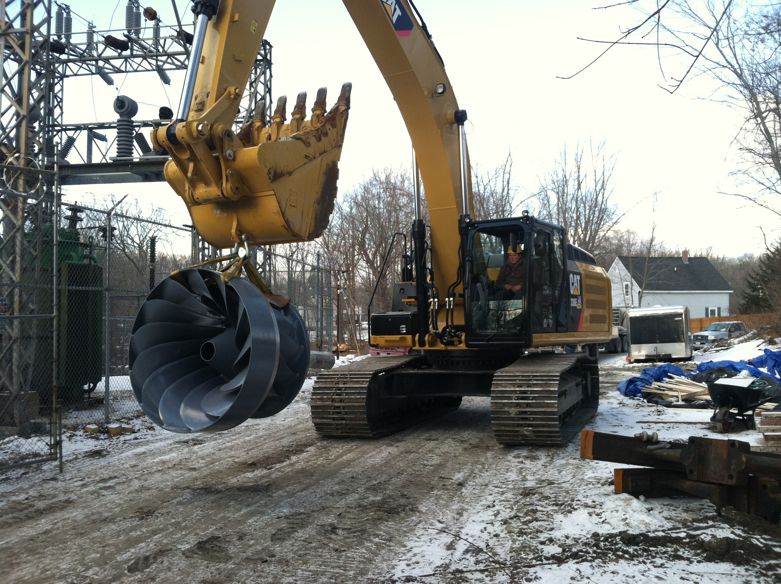
A birds eye view of the
discharge end of the new runner.
Both pieces ($450,000) are
tucked safely away behind the fence.
January
16th, 2013, added the following sidebars:
Added,
"Erection and Alignment of Vertical Waterwheel Generator Plants"
by R. O. Standing, Niagara Falls, Ontario, January 15th, 1951.
Added,
"Hydraulic Turbine and Governour Field Erection Information",
NEMA Hydraulic Turbine Section, June 12th, 1953
Added,
"Generator Shaft Design Calculation", Olav Hodtvedt, September
20th, 1985.
December
30th, 2012
Added
sidebar: Admitting Air to Turbine Runners Improves Efficiency,
S. Logan Kerr
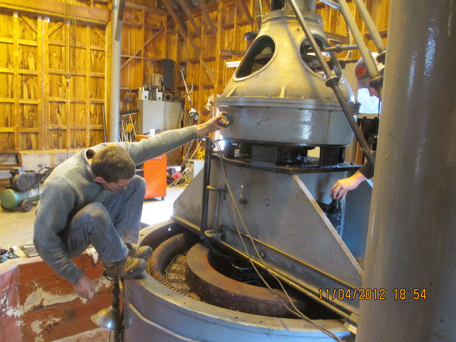
Will and
Celesty have taken apart the little GE generator. It started
making a thumping noise. They found out the gear pump that
circulates the oil in the lower radial bearing had failed and
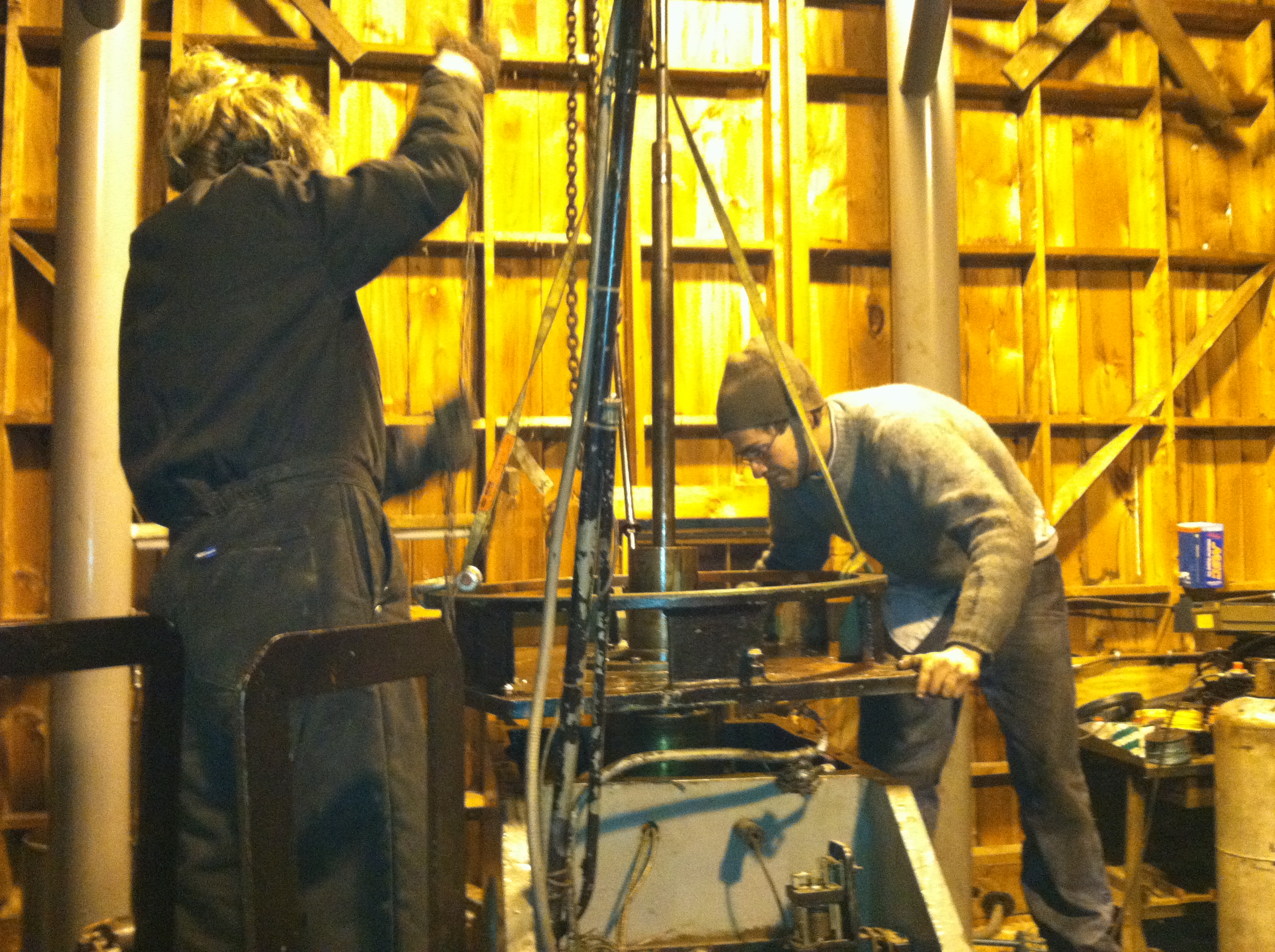
the babbitted bearing seized. Here they are removing the cover
from the thrust chamber.
Here, they
have dismantled the Kingsbury bearing chamber to inspect the
upper radial bearing and thrust shoes for signs of damage that
may have occurred from the lower bearing failing.
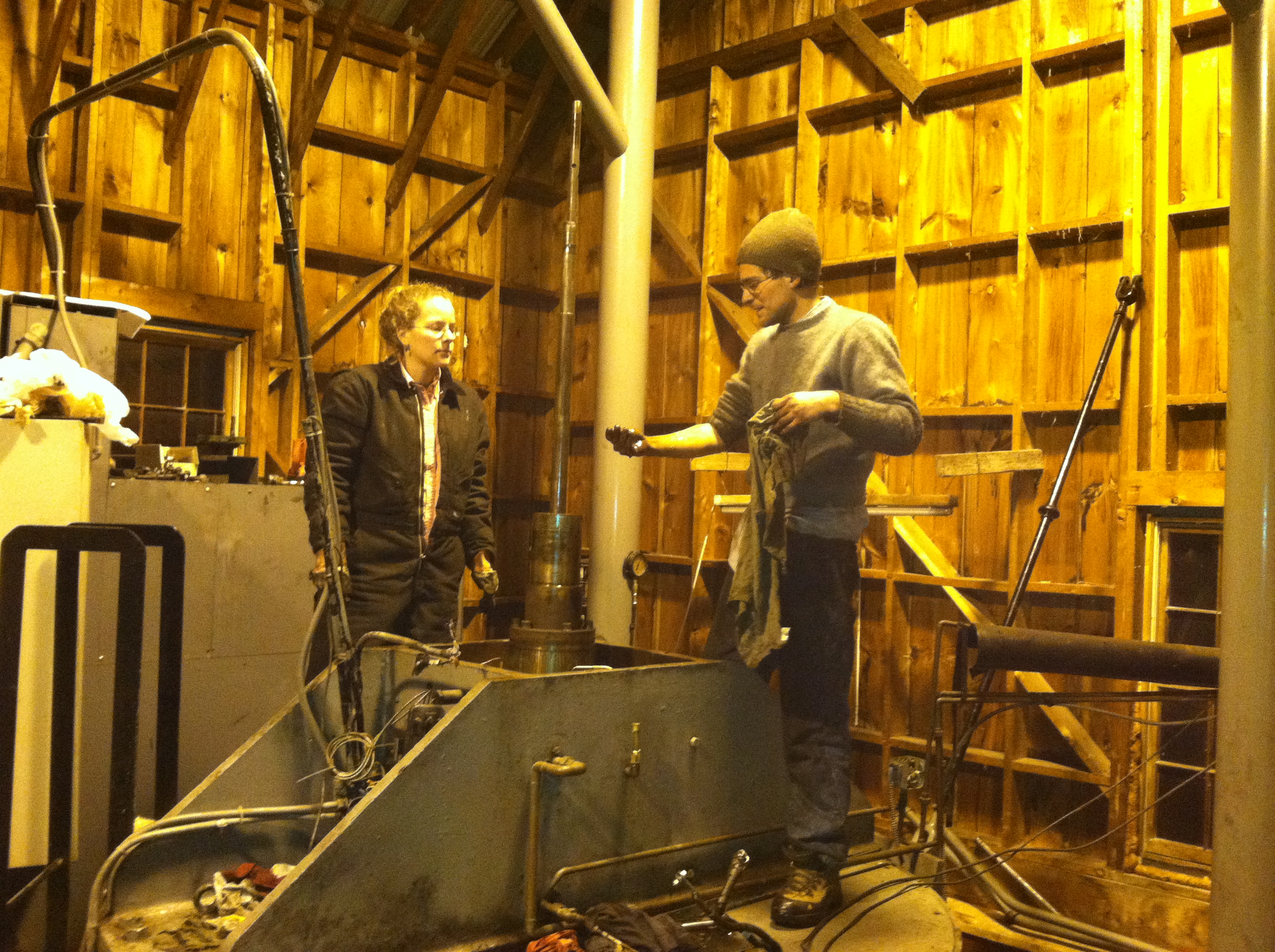
Celesty
and Will have just rigged down one half of the lower radial
bearing oil pan. The powerhouse is being kept above freezing
with a propane mushroom heater. The heat does not penetrate into
the wicket gate chamber. It was really cold. Will's hands are
turning blue!!
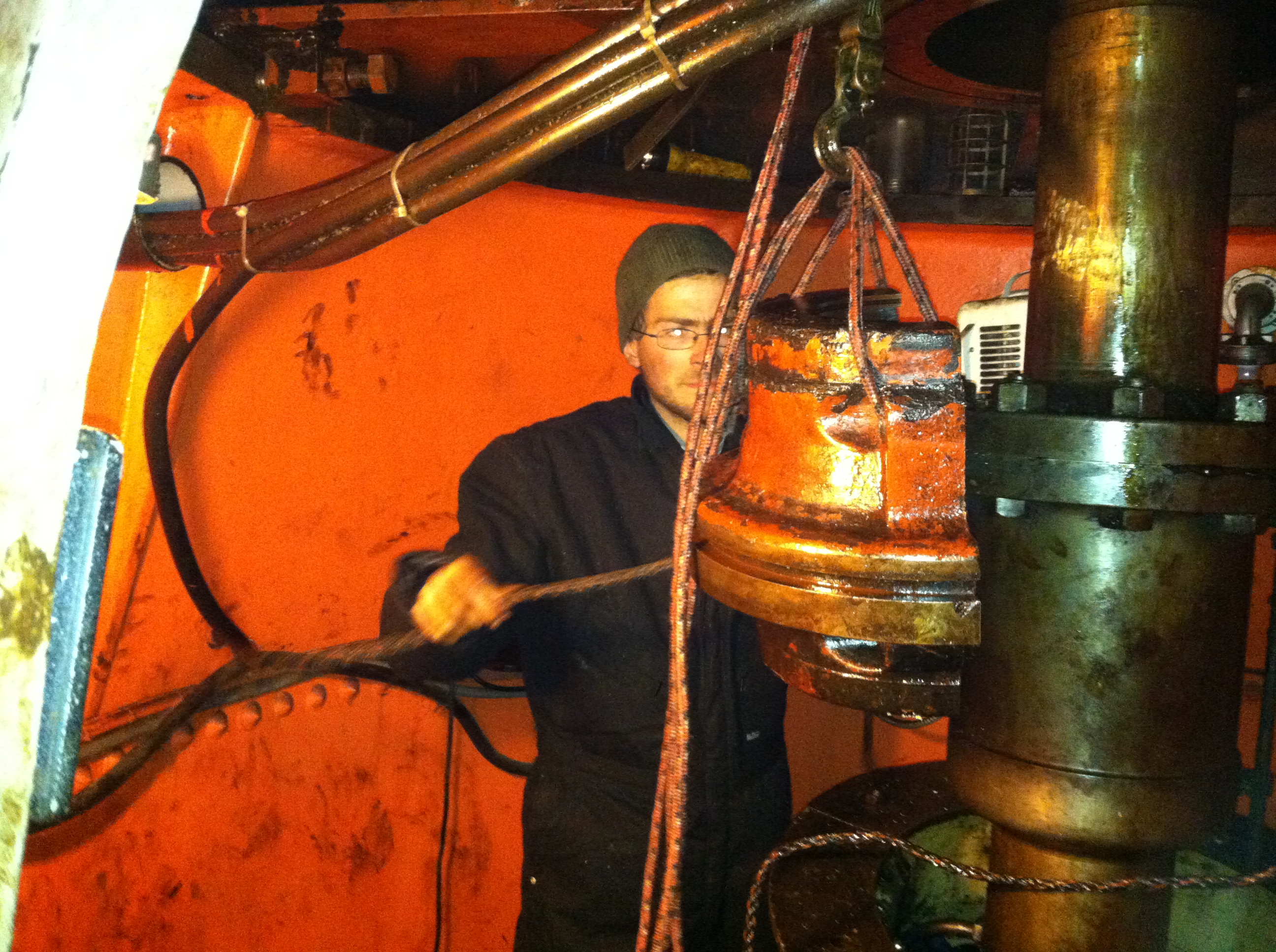
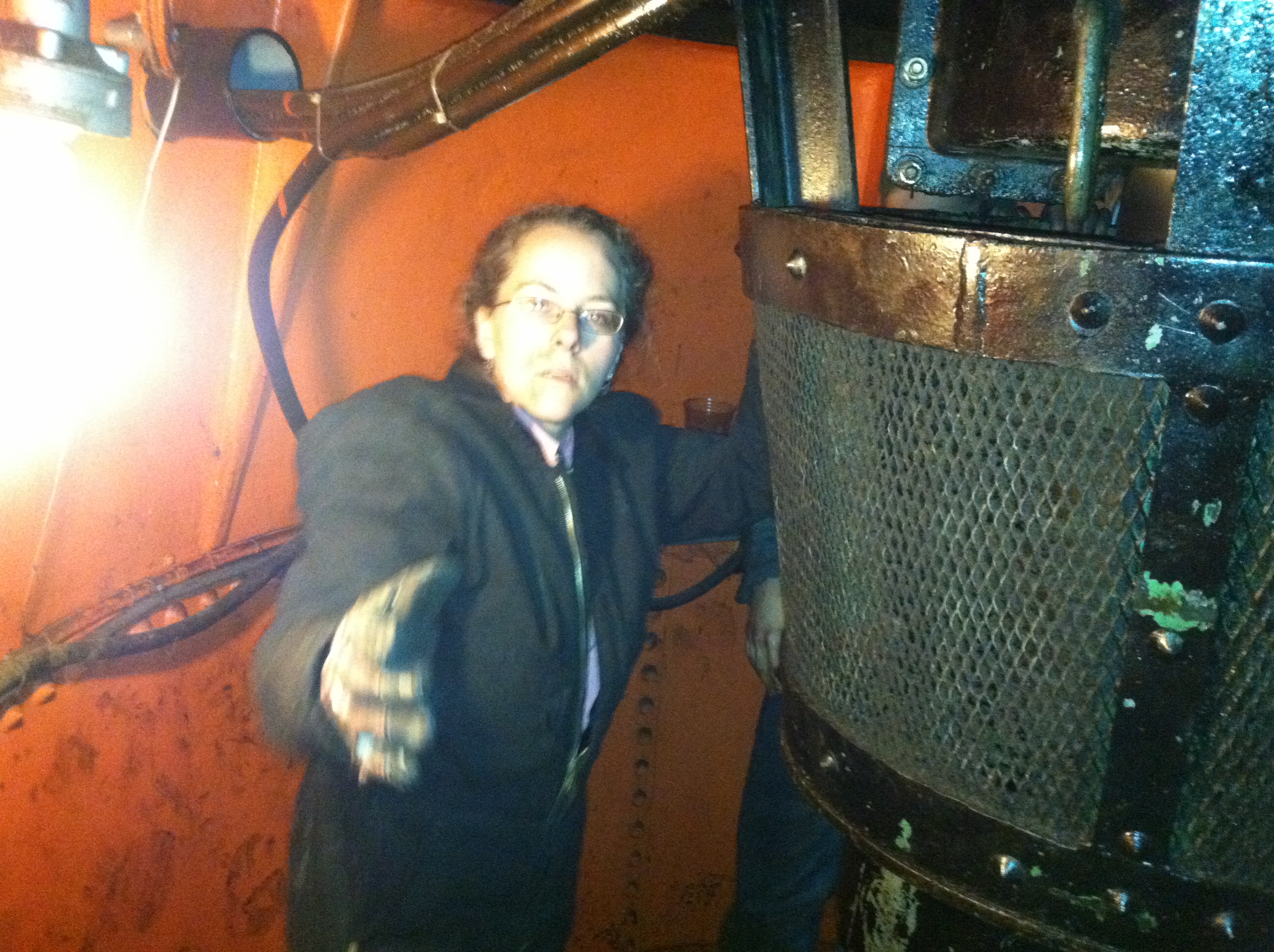
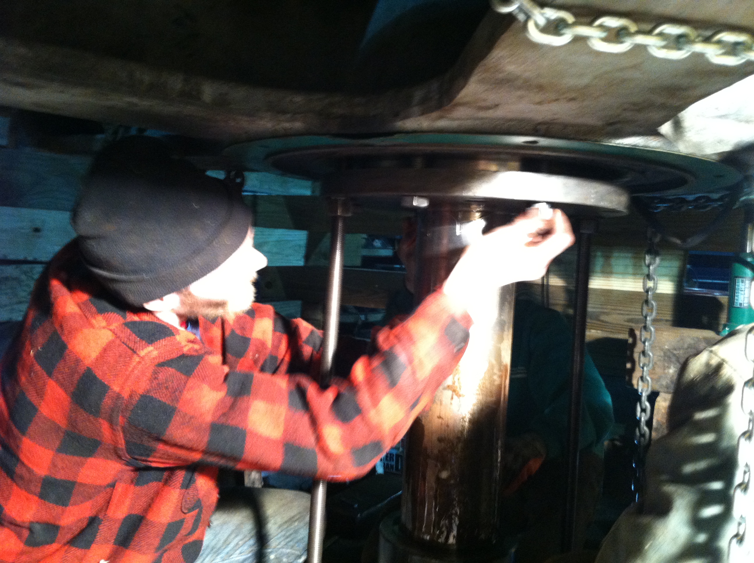
Here, Will
and Celesty have jacked down the lower radial bearing and split
it in half. They have removed one half and are rigging the
second half out from under the generator. What a greasy mess!!
Each half ways about 150 pounds.
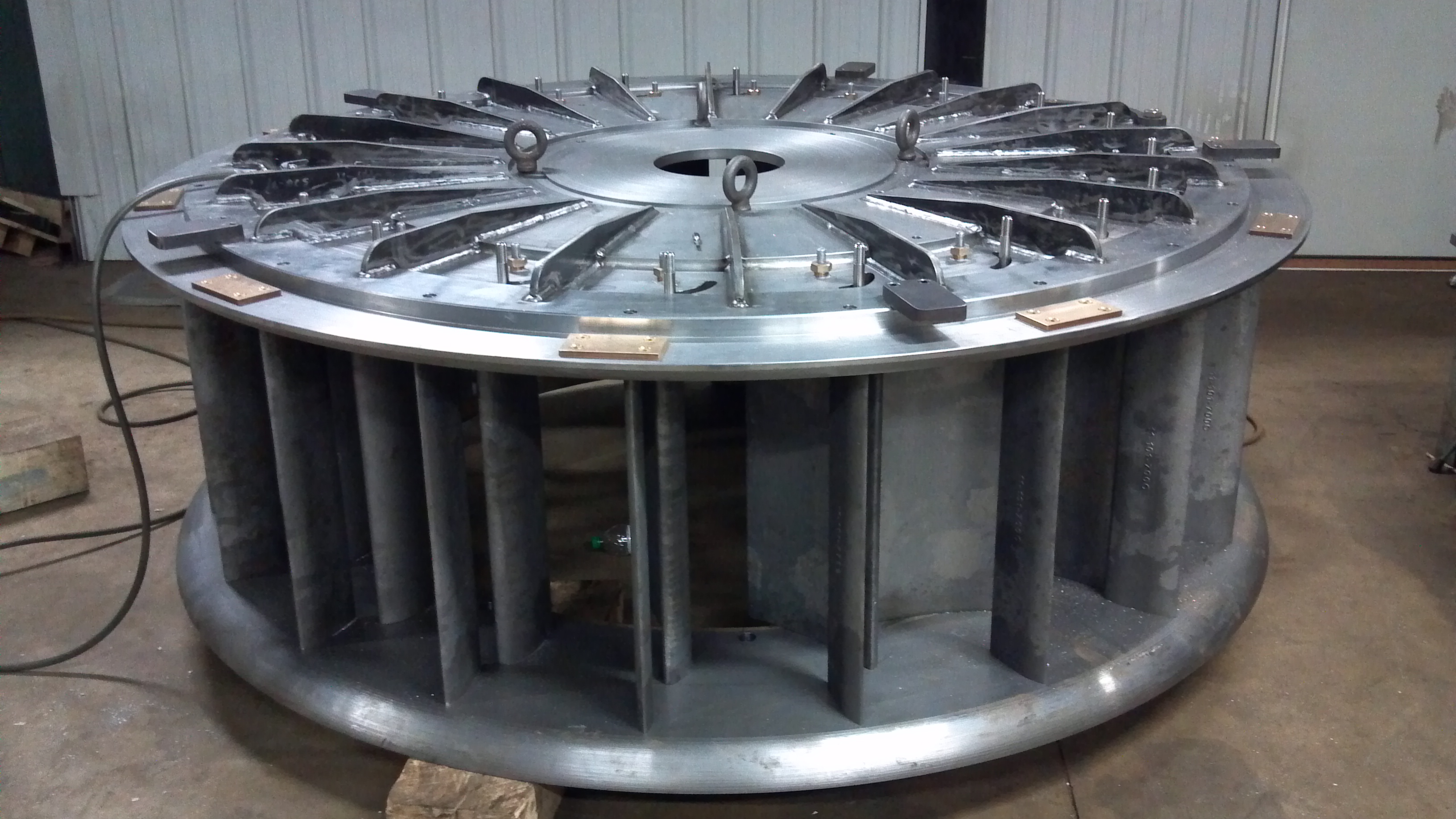
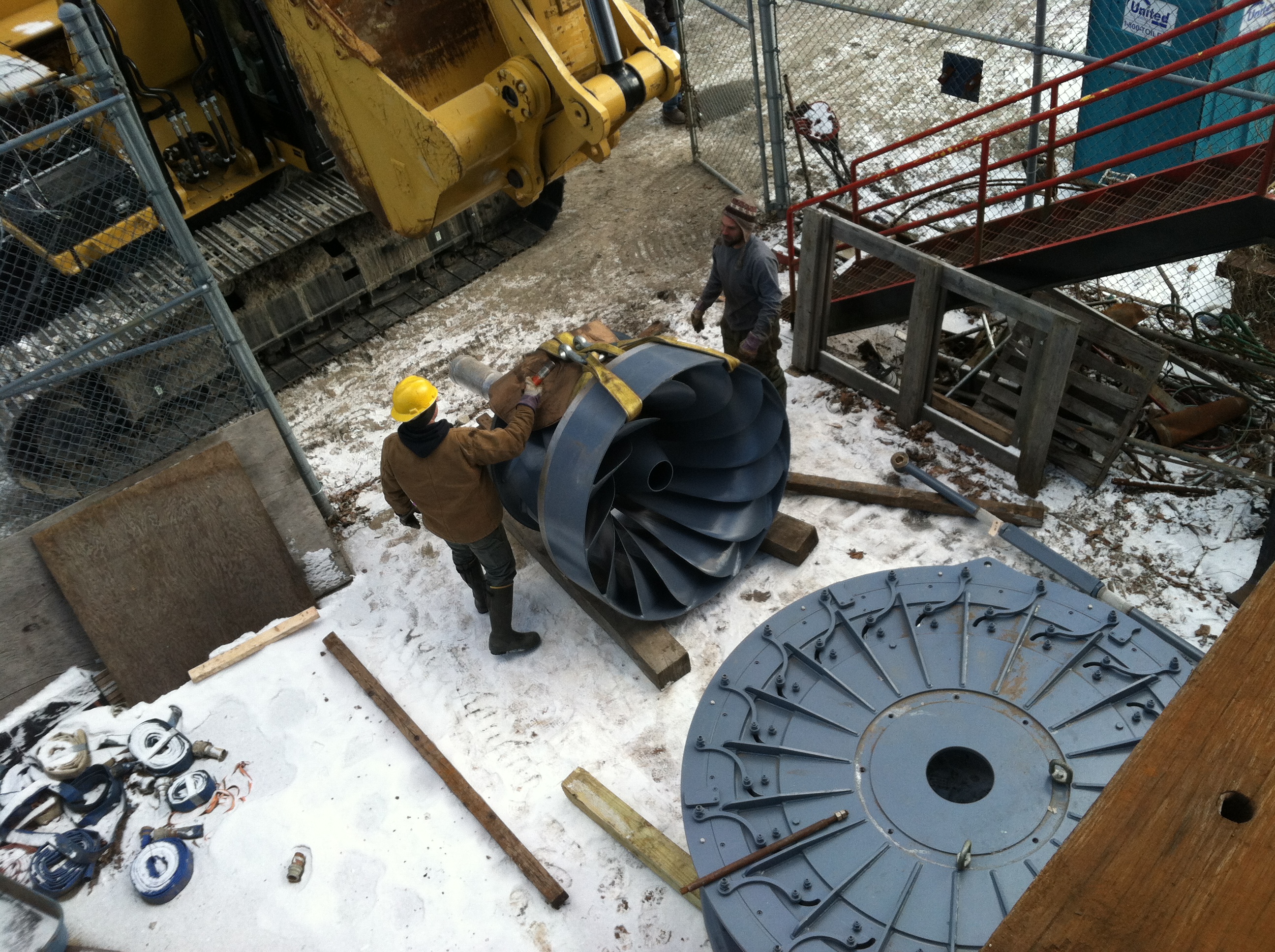
Here is a
photo of our new Kiser stainless steel gate case. Note that both
the outer stay vanes and the wicket gates have been fitted to
the crown cover and stay ring.
Here is a
photo of our new Kiser stainless steel runner. They have just
turned the outside circumference of the crown of the runner and
the outside circumference of the skirt ring.
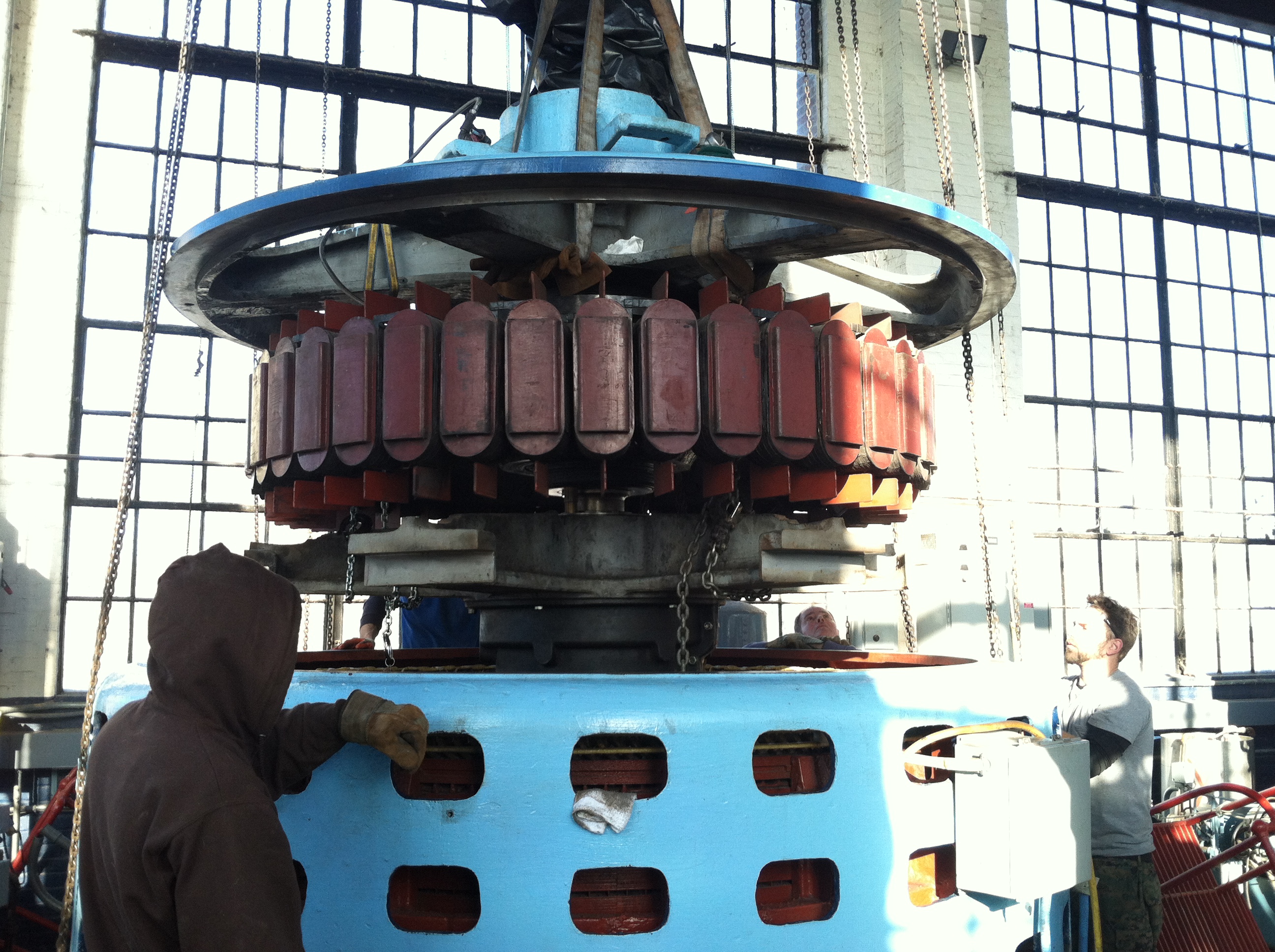
We are
preparing to fly the Number One Generator over to the Number
Three generator pedestal. We are getting ready for when the
penstock will be done at the end of January. The new, Kiser,
runner and gate case, delivery got delayed to mid November, then
to mid December and now it is supposed to be delivered in early
January. We need to have at least two units operational so we
are marrying the good generator to the good turbine. When the
Kiser turbine comes we will install it in the turbine pit. Then,
when the rebuilt Westinghouse generator comes back from Maine,
we will install the rebuilt by Stoltz Electric generator to the
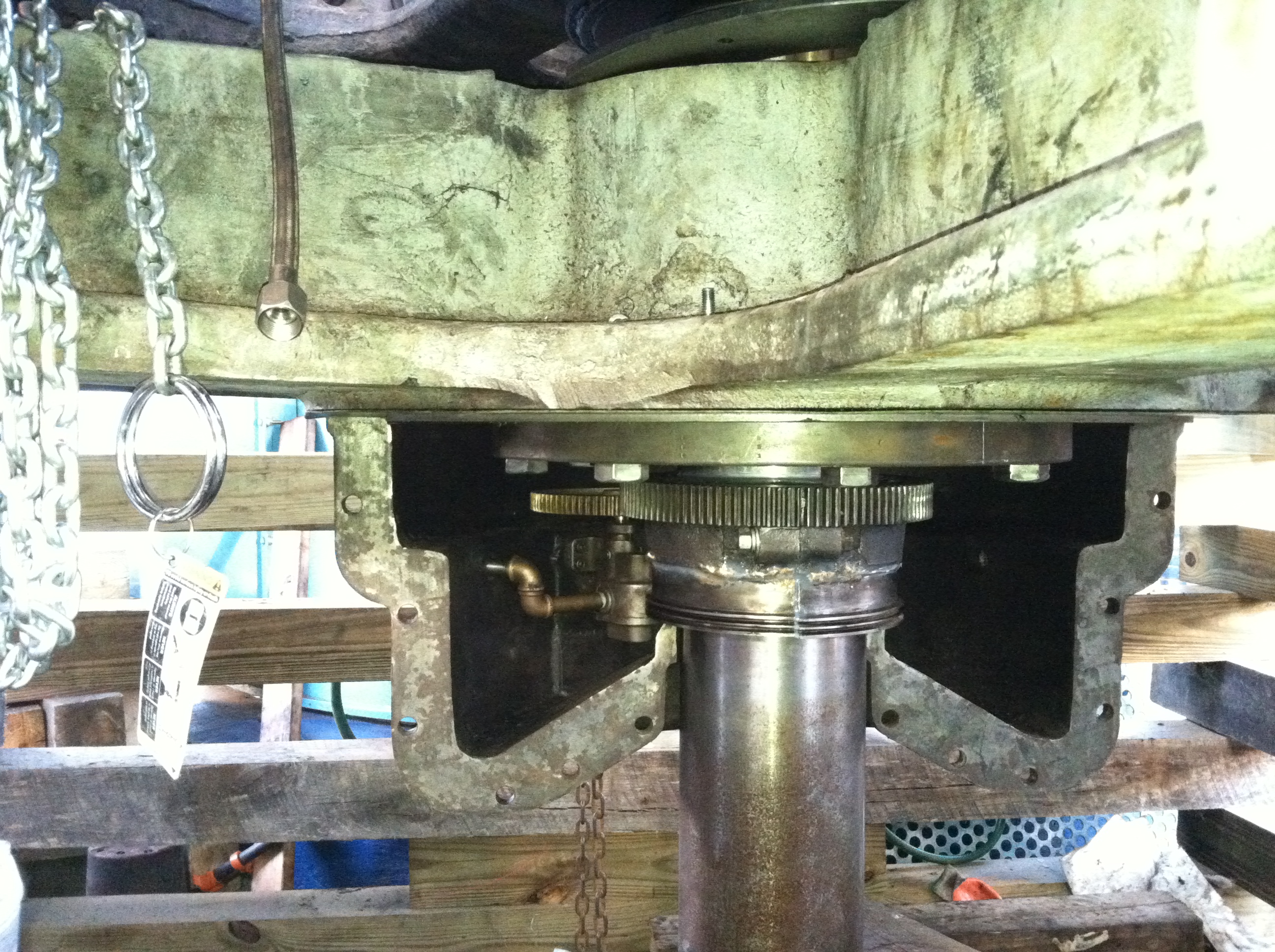
new Kiser turbine. This is a view of the lower guide bearing
with the lubricating gear pump installed and half the crankcase
installed.
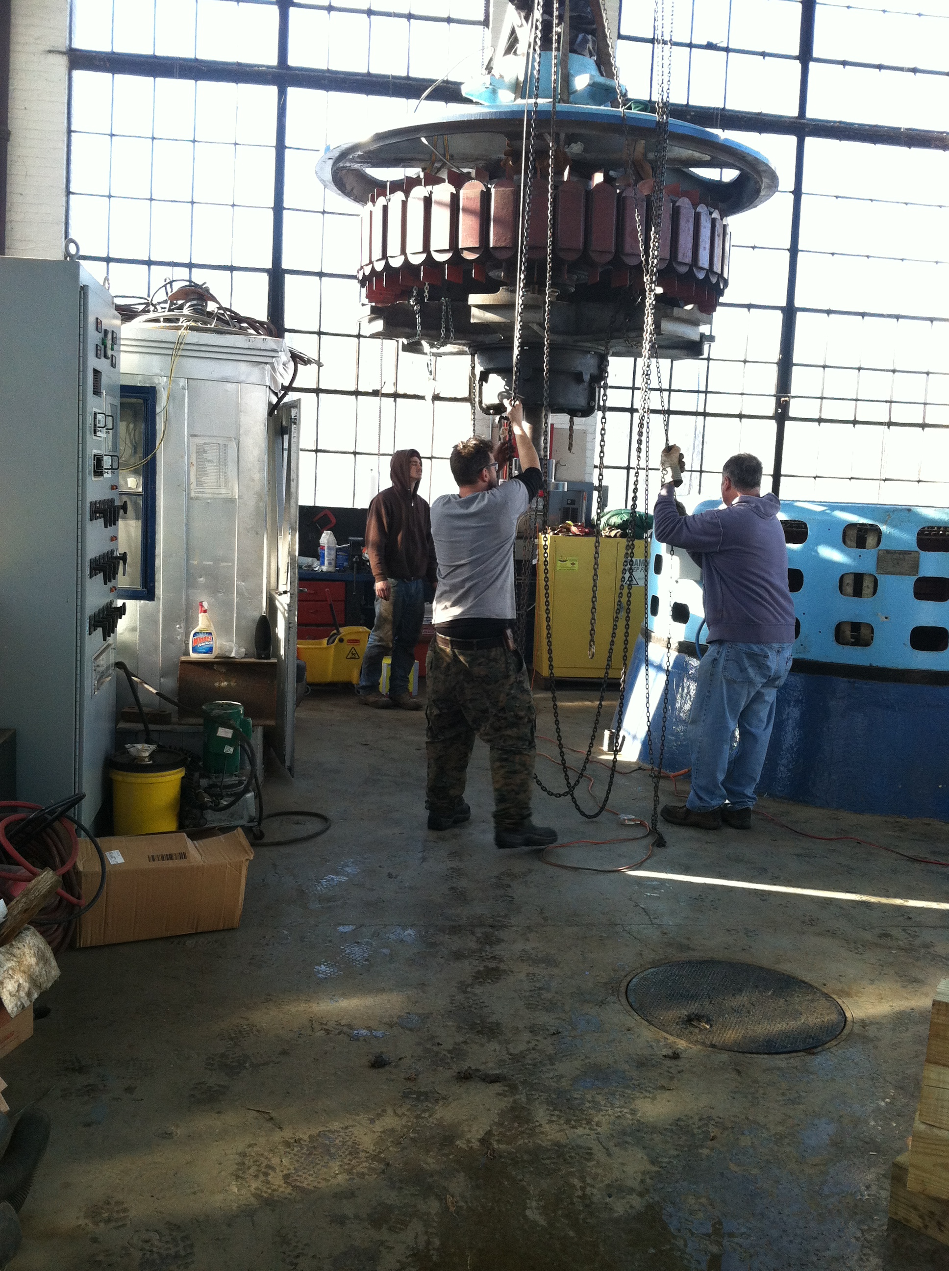
We are
flying the newly assembled rotor to its new location.
The
rotor is almost down!
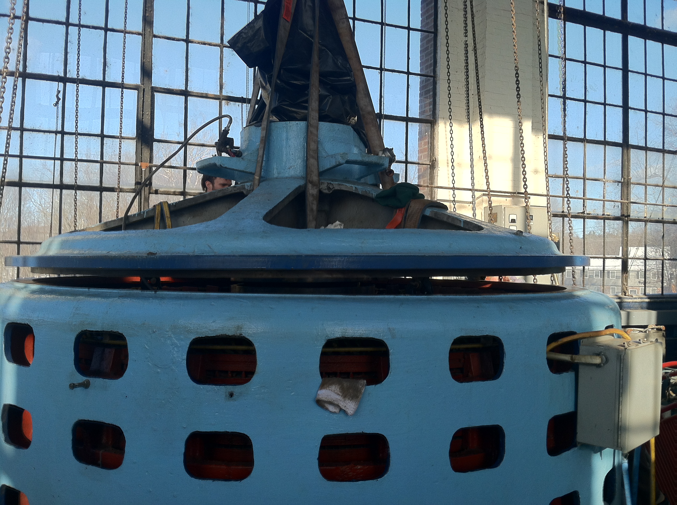
The last
adjustments are being made.
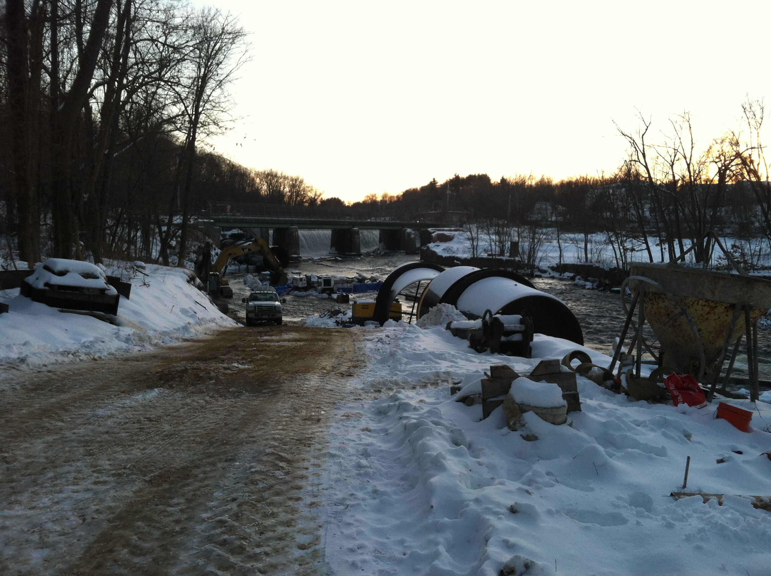
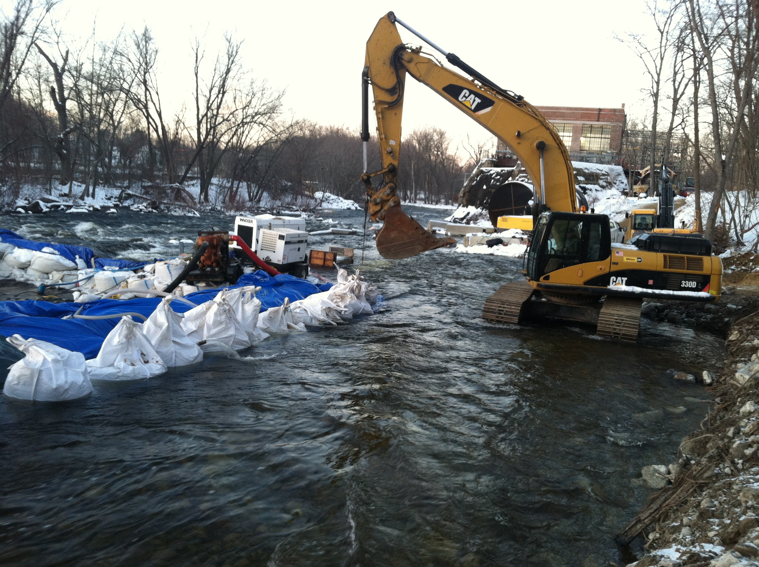
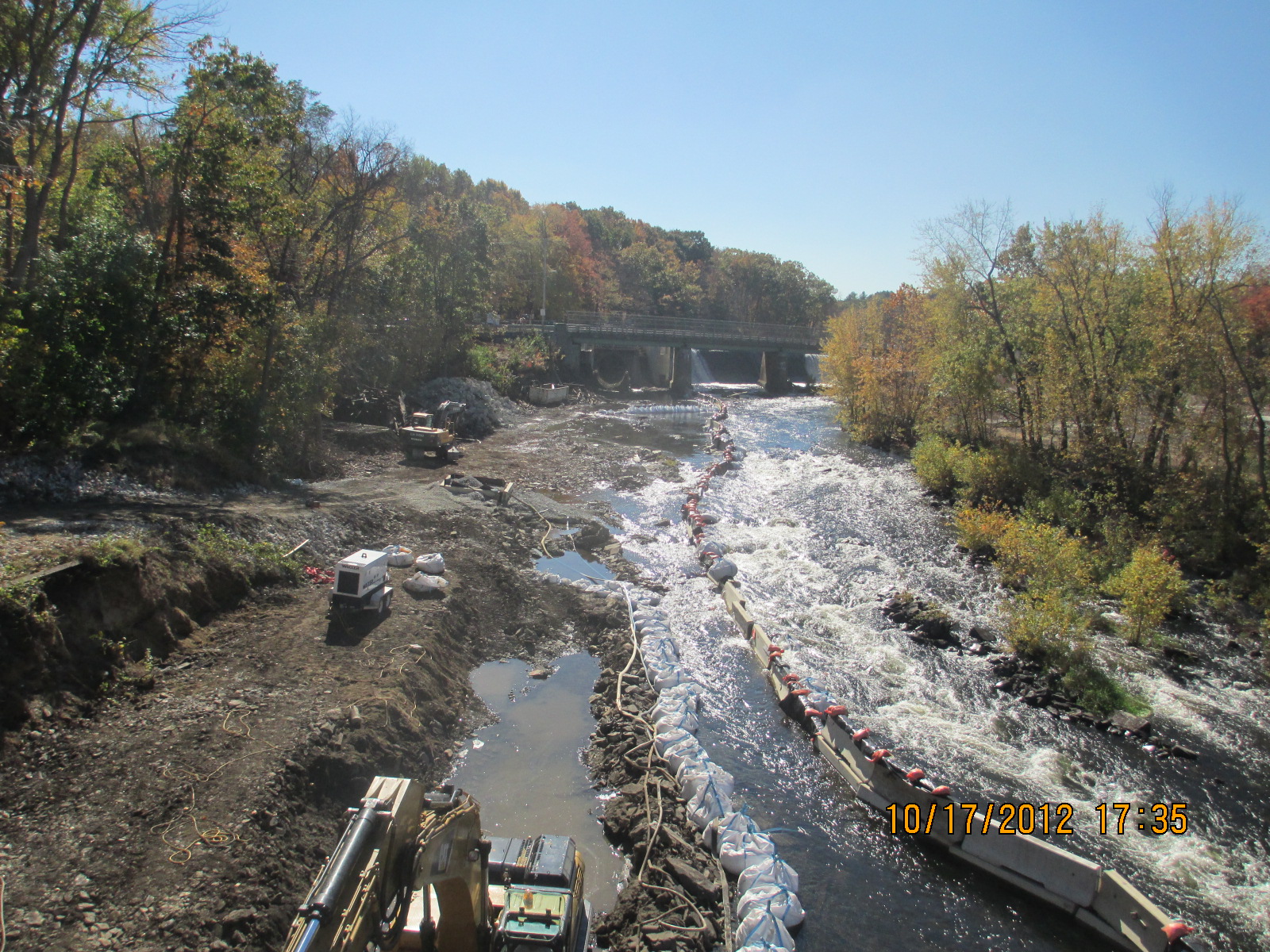
The
contractors, North East Infrastructure of Hudson, MA. are making
progress on the penstock. The river has come up and they still
need to pour the last two penstock footings. They have made a
circular coffer dam in the river bed and have been continuously
pumping it out while they build the final set of forms.
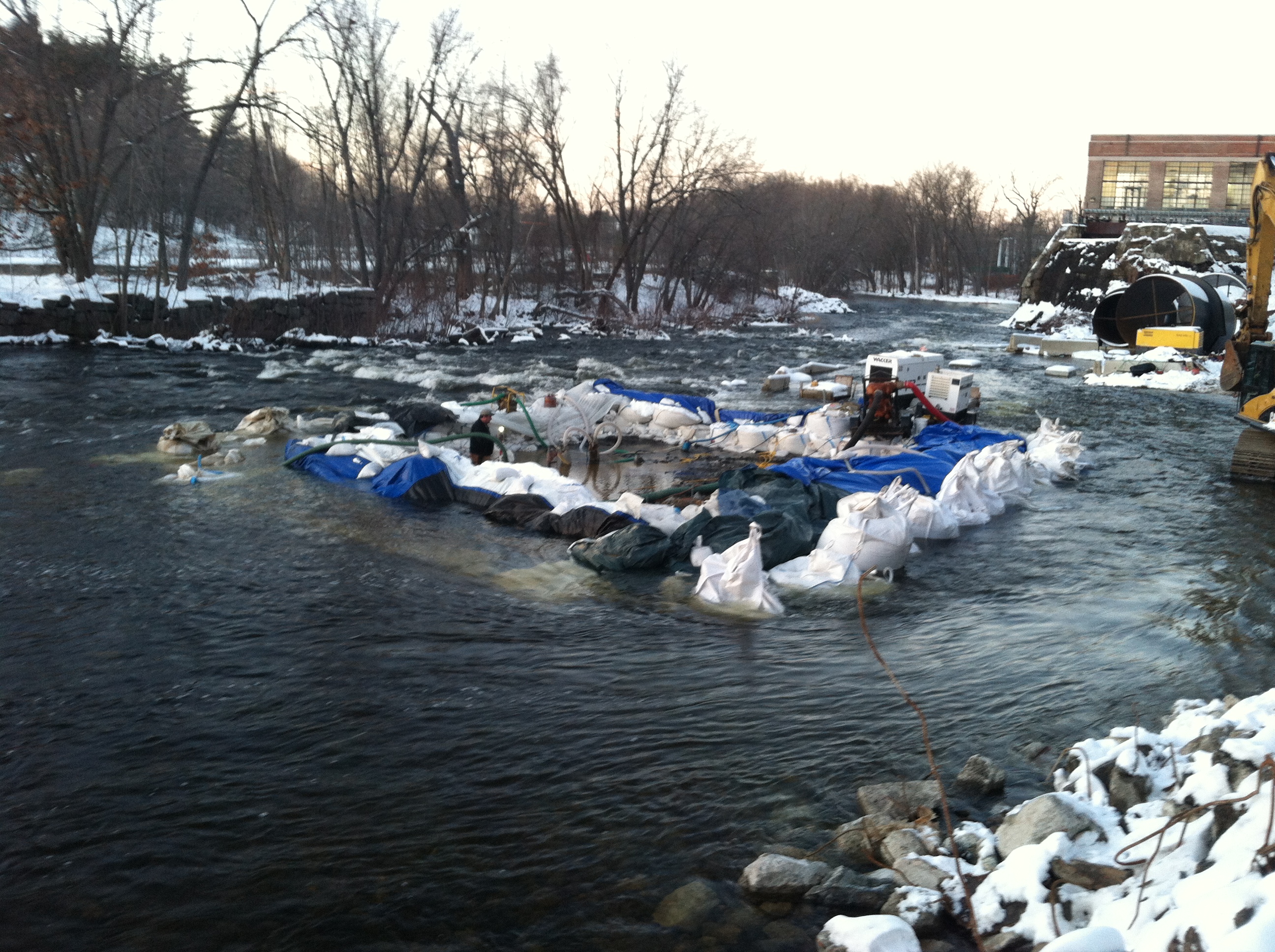
Look at
these heroic guys working in the middle of a river, with 700
square miles of drainage area, during flood stage and its 18
degrees Fahrenheit!!! The foreman and driving force on the
project is Brad Baker. He is an ex US Marine Sergeant who
learned how to command men. He is easy going and very polite but
when he wants something done his crew does not hesitate. He and
his crew are tough as nails. That is him manning the pumps.
Previous to this I watched him walk across the five foot deep
water, in full waders and climb over the wall of the coffer dam
like it was a walk across the parking lot on a sunny day!!
Another view of the coffer
dam.
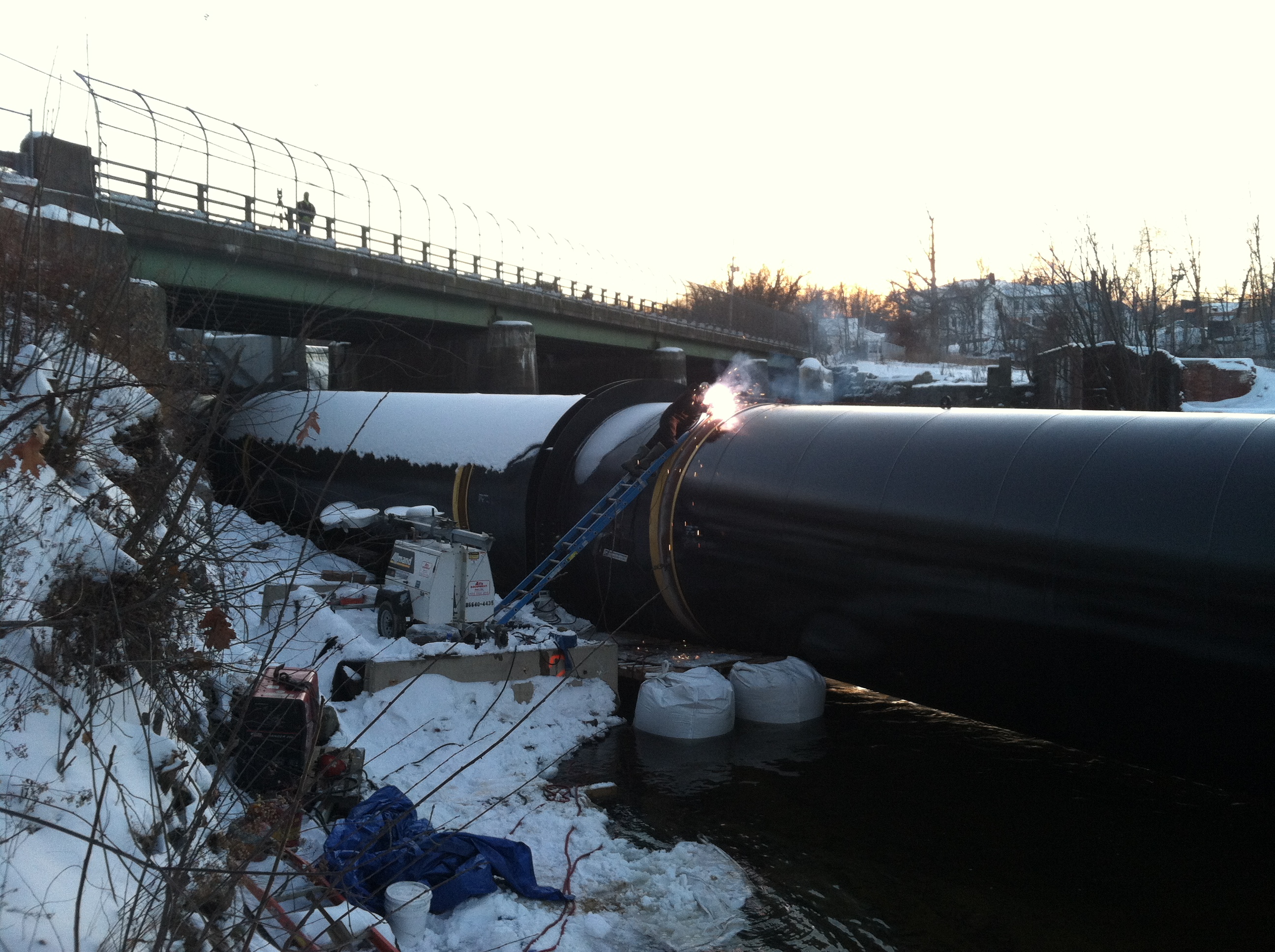
This
poor welder is doing all of the welding on these 45 long joints
inside and outside.
We tickled
the big girl's exciter but there was no current. Will is
inspecting the brushes on the slip ring. He stoned the slip ring
surfaces until they were bright. We tried to excite her again
and the current came right up to 60 amps DC.
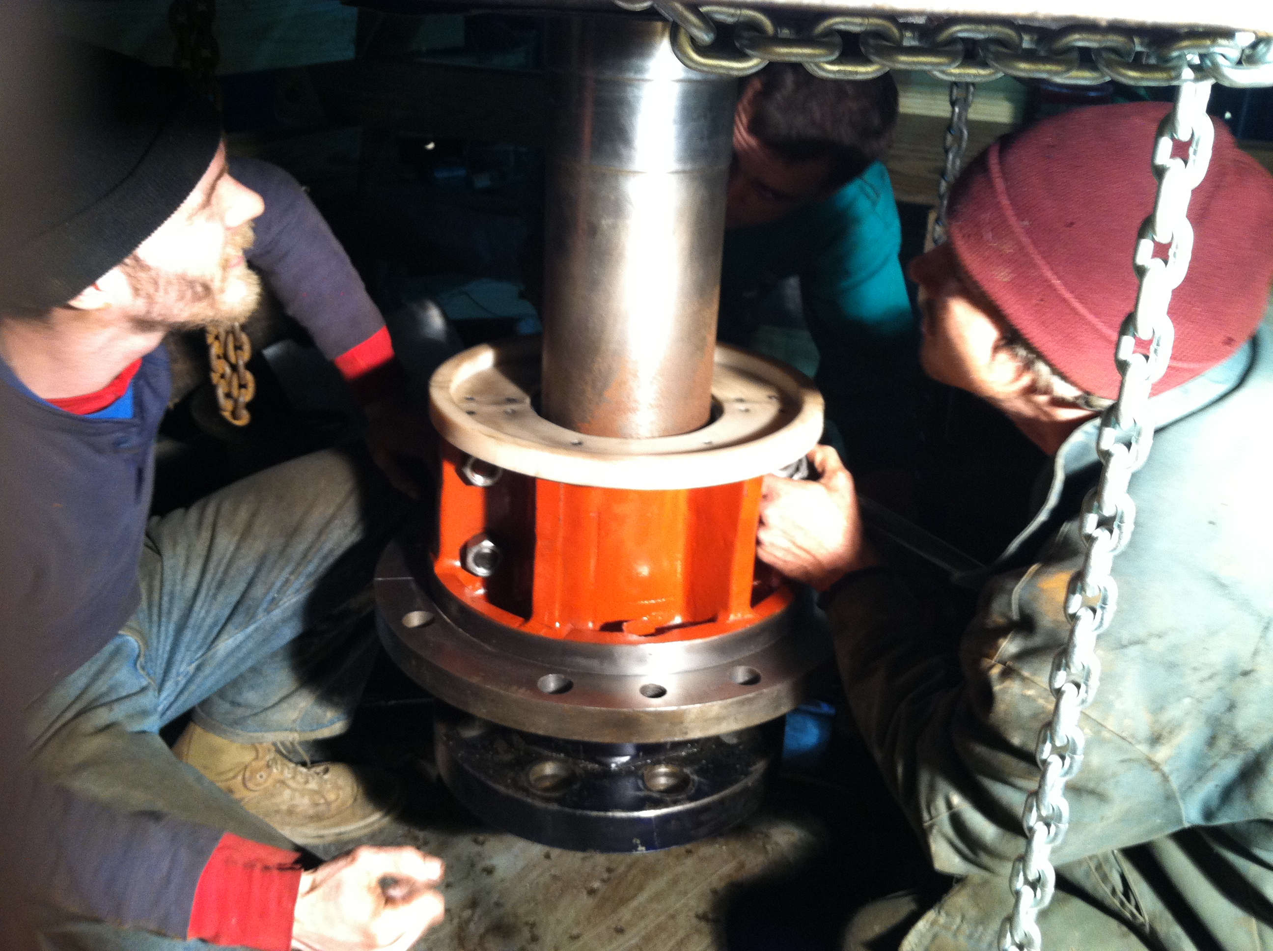
Here, Mike
Desrouche and John Remington are crouching beneath the No. Three
rotor. They have bolted the two halves of the lower guide vane
together in preparation of raising it into place with threaded
rod.
Here they
have raised the bearing into place on four threaded rods high
enough so that John Remington can install the ring of 0ne inch
bolts
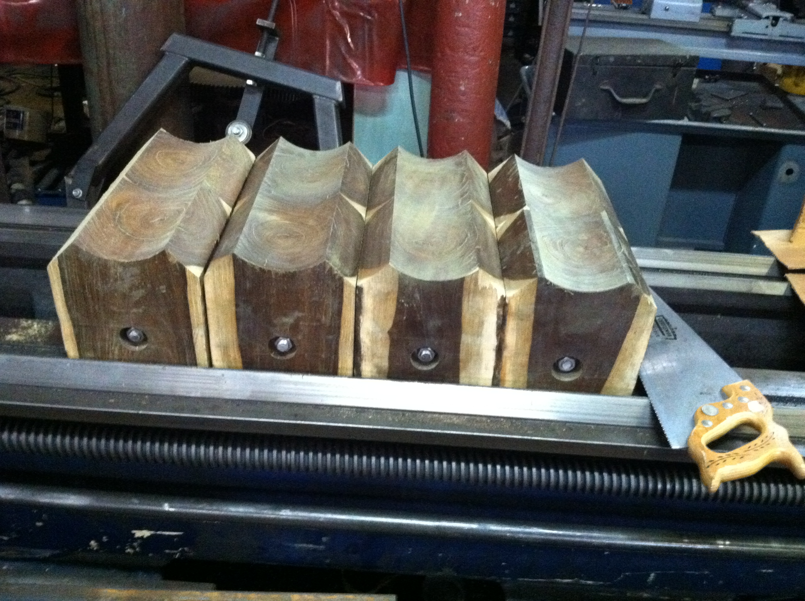
Here are
four newly minted Lignum Vitae quarter blocks. They Lignum Vitae
arrives in the shop as a log. Warren cuts them into end grain
blocks. He machines the blocks and cuts tongue and grooves into
the sides of the blocks with the big Cincinnati milling machine.
He spreads glues on the tongue and groove sides and compresses
them in the 150 ton hydraulic press. After they dry, he line
bores them with the Lucas horizontal boring machine and installs
the threaded rod tie bolts. Finally, he mills off the corners.
If you do not mill the corners off, the longitudinal corner of
the wood wedges itself into the edge of the cast iron quarter
block assembly and tears the cast iron asunder.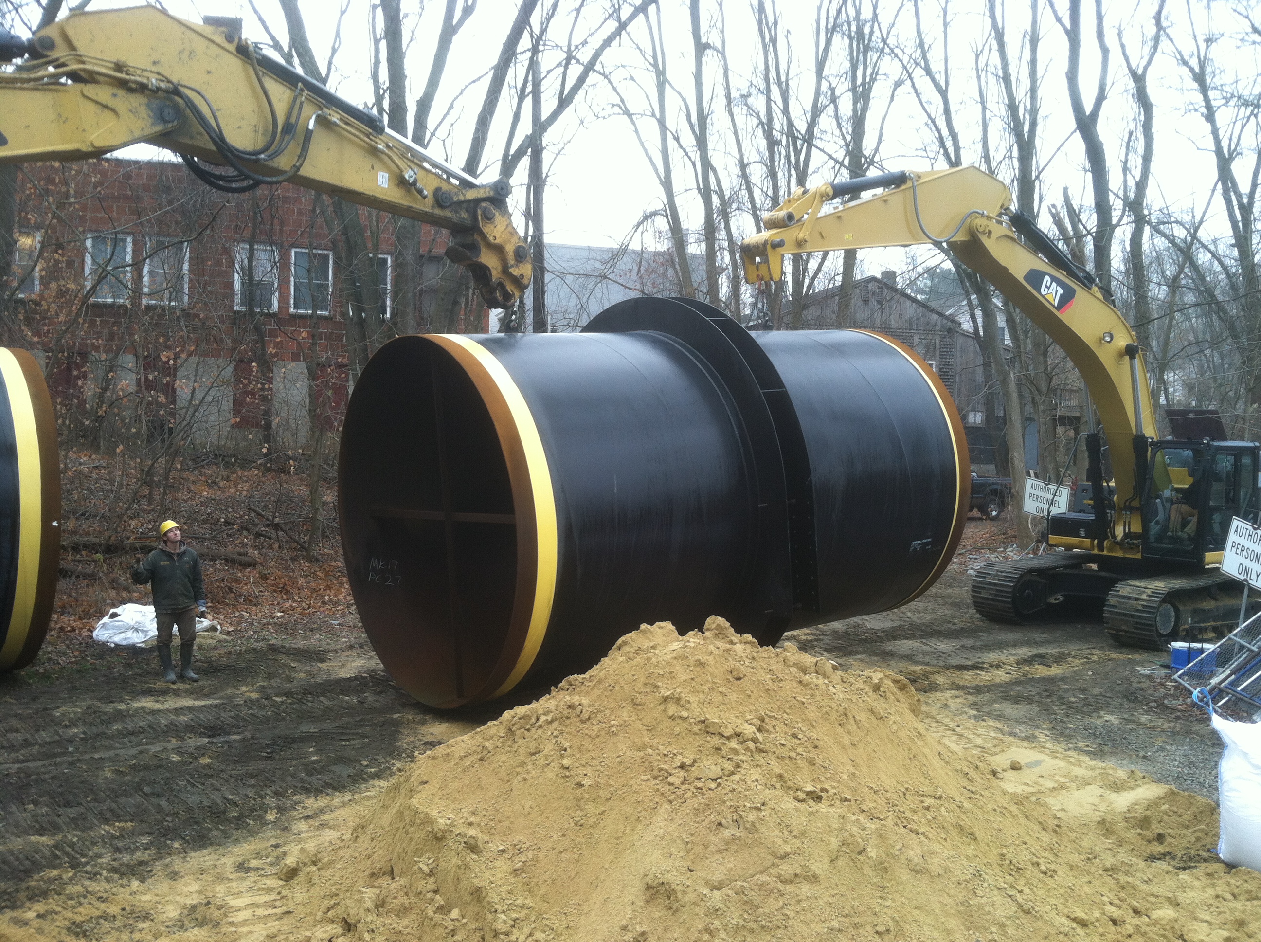
Two giant
excavators moving a piece of new penstock.
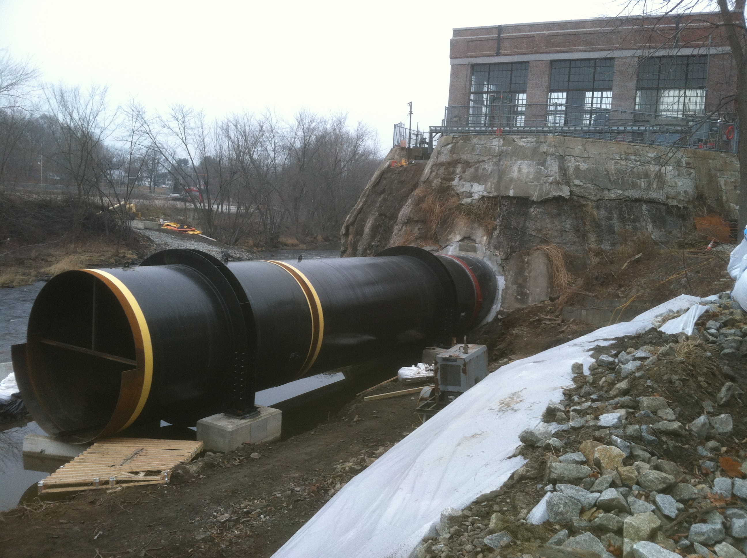
The
penstock is slowly moving along in spite of high water. Note the
pipe is supported by ring stiffeners mounted on concrete
footings.
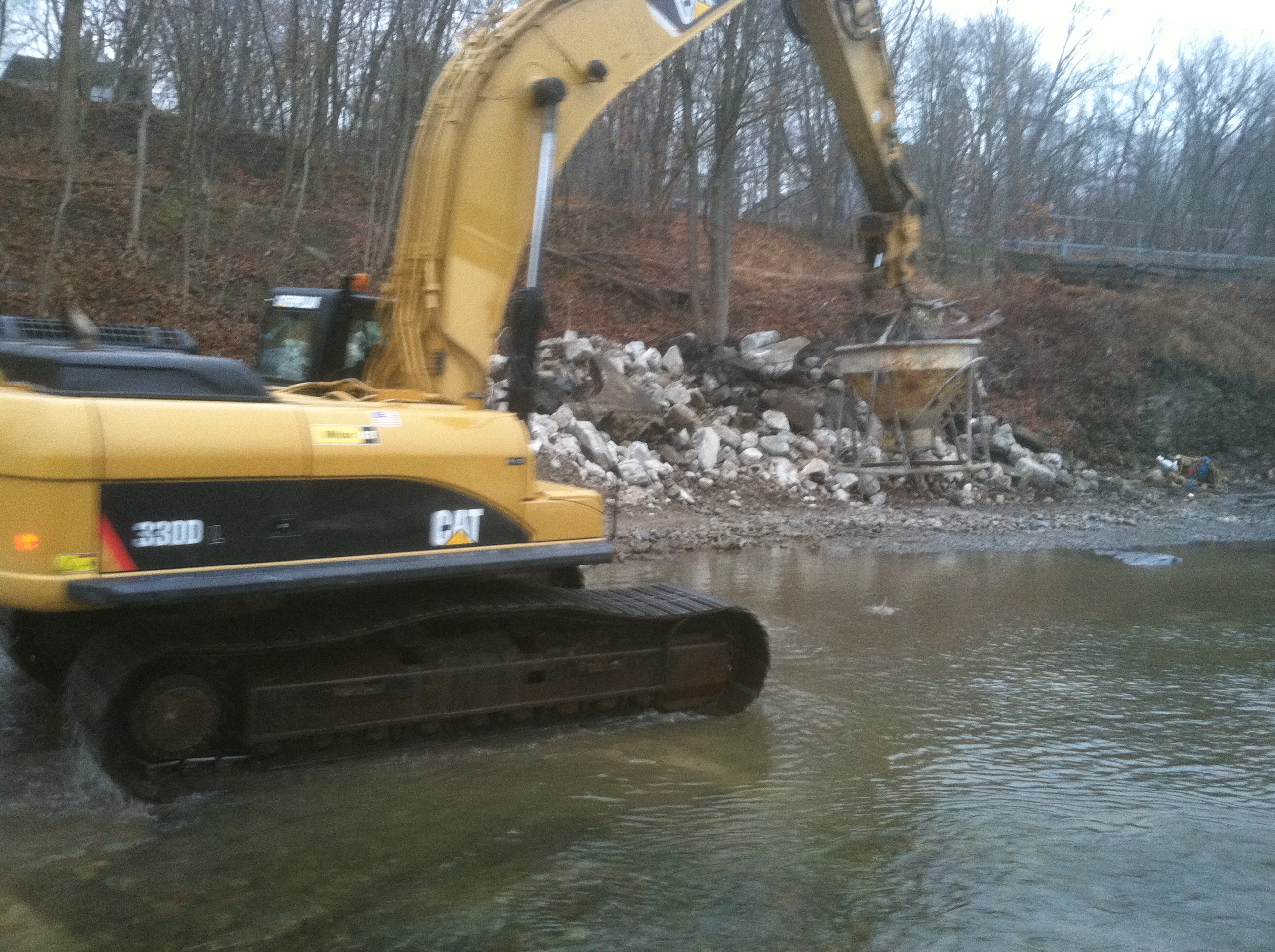
The
excavator is bringing a bucket of concrete up the river to a
penstock footing form.
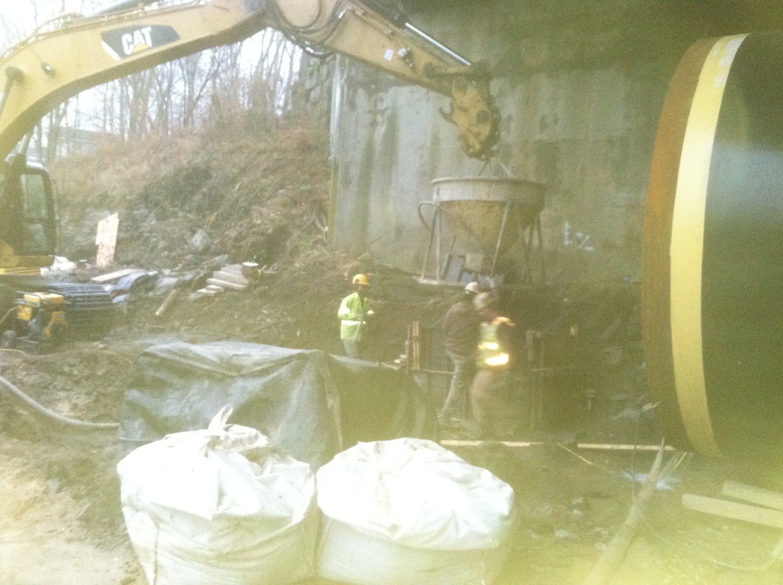
Poor
picture of a pour. The guys are vibrating the concrete into the
form as the excavator drops the concrete out of the bucket.
October
29th, 2012
Pepperell
Penstock Replacement:
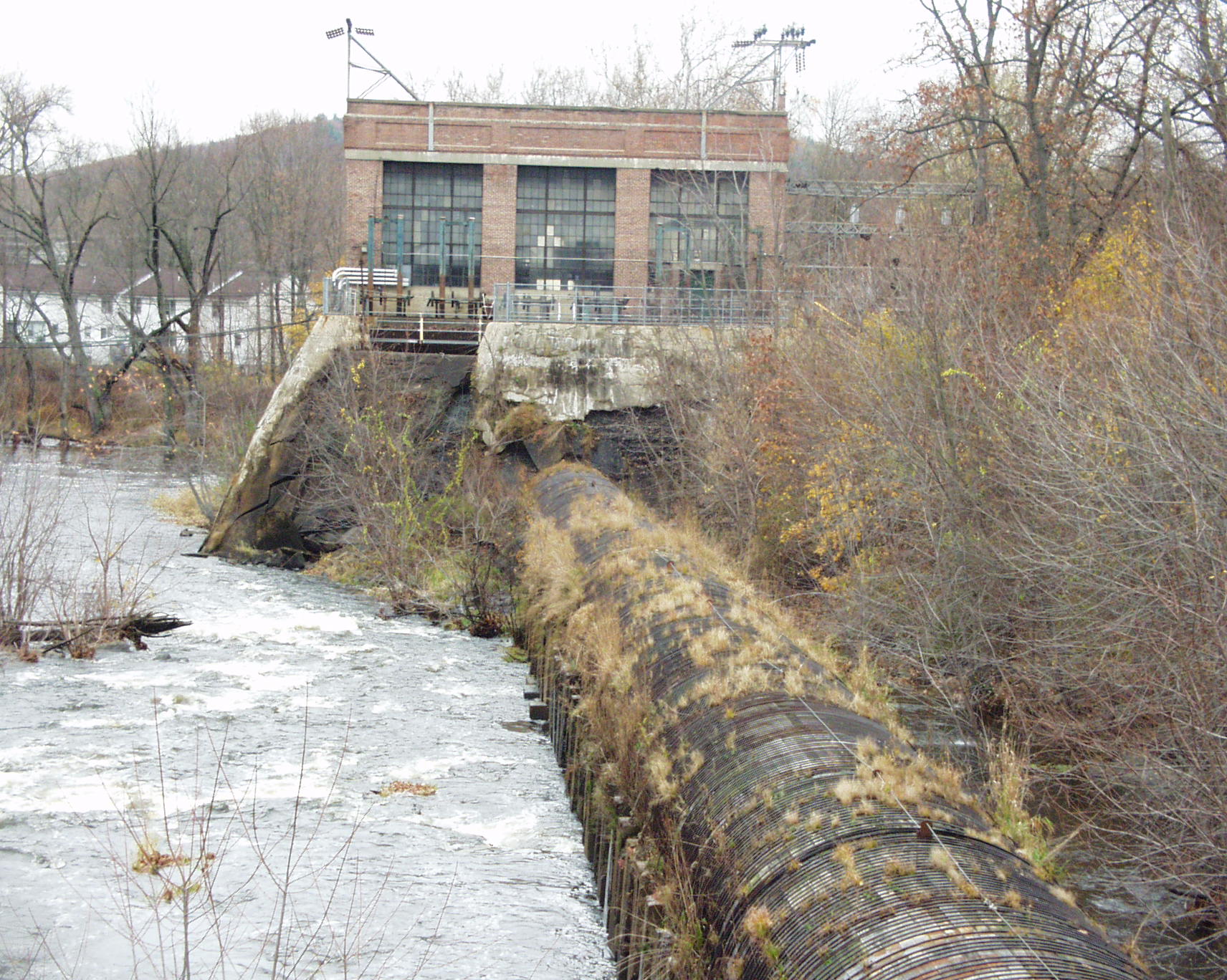
Here is our grody old wooden penstock. It is 500 feet long and 13 feet in
diameter. It has concrete cradles every six feet to support the
weight of the water. It is 70 years old and causes us to lose
sleep at night. We are spending $ 5,000,000 to replace it in
steel and make other improvements.
Here the
wooden penstock is gone. The Jersey barrier coffer dam keeps
most of the water out of the work area.
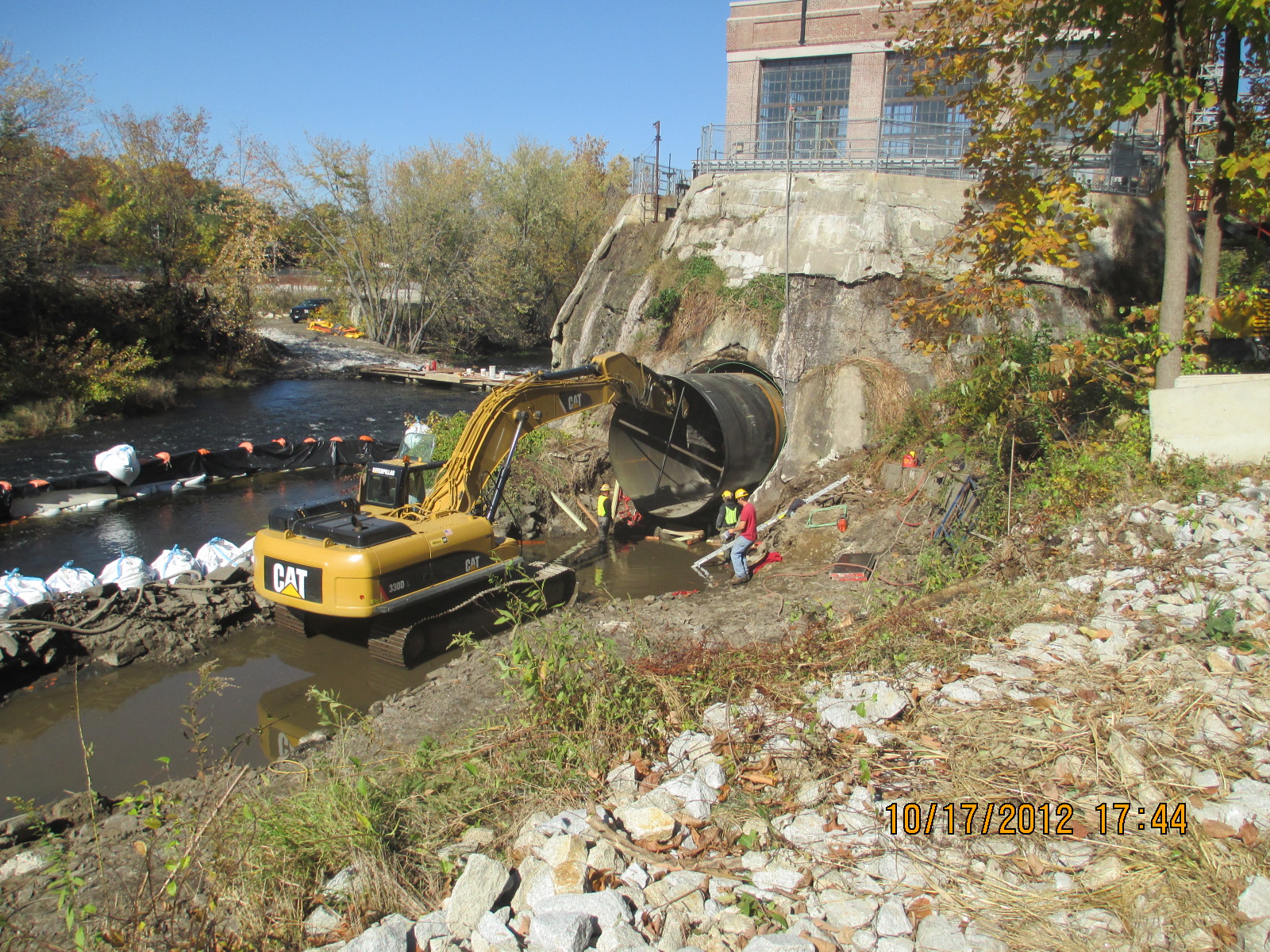
Here this
enormous excavator is attempting to install the steel adapter
piece into the forebay wall.
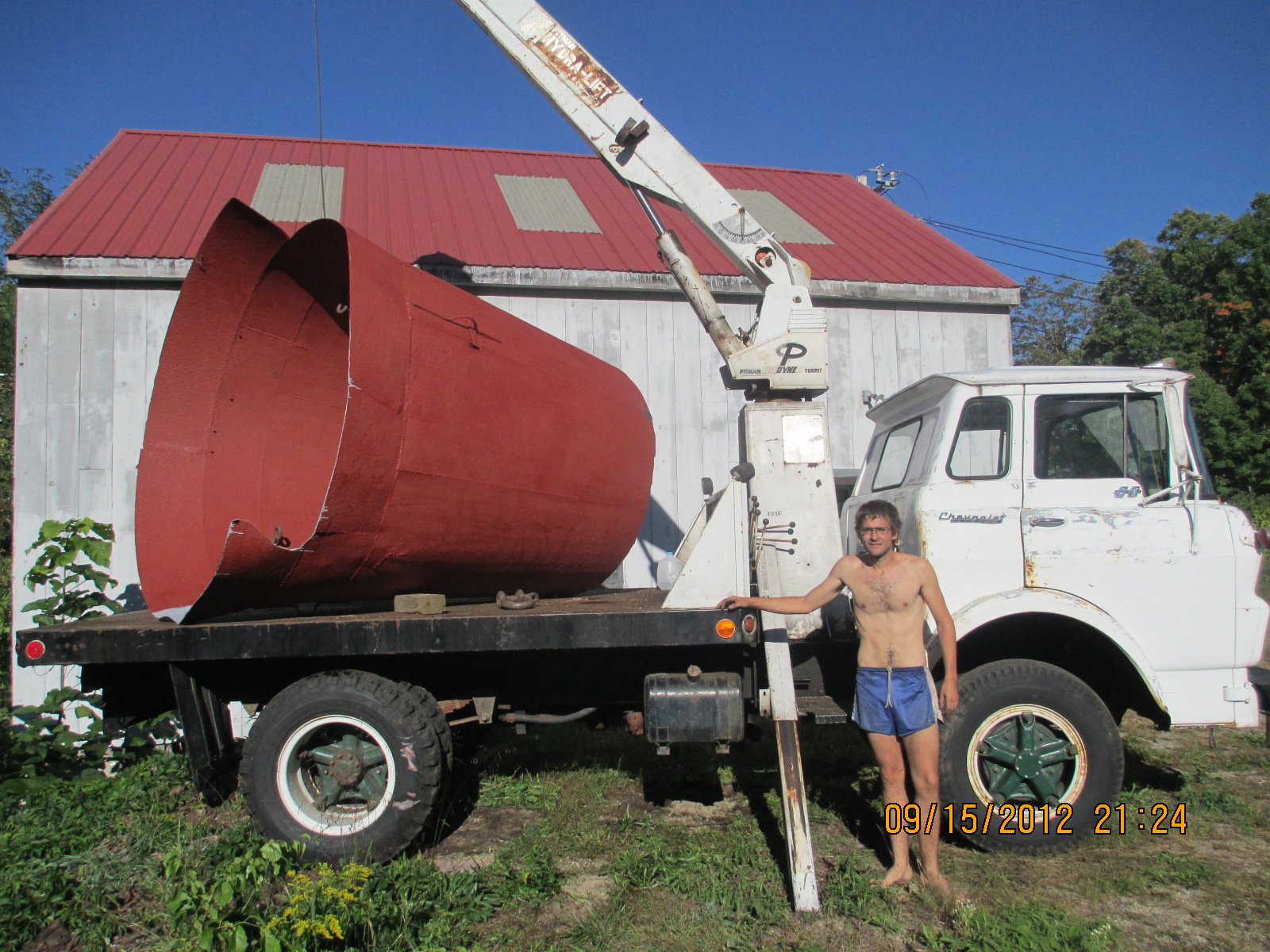
Draft Tube
Rebuild:
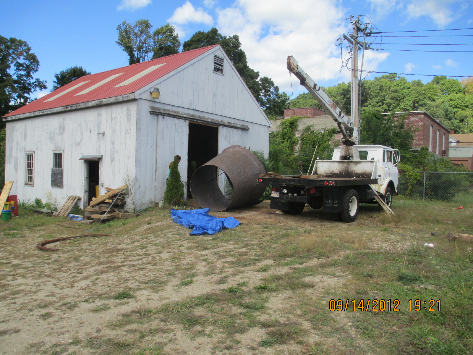
This plant
had its draft tube fall off.
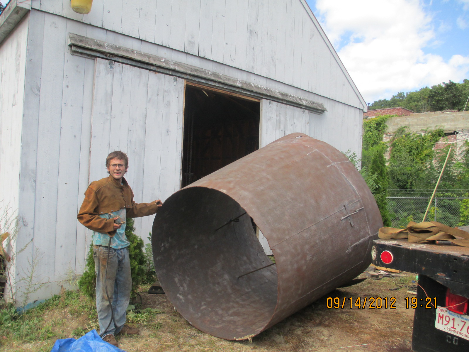
Will has
de-scaled the draft by sand blasting it with black beauty. There
were many sections that had broken off. Will went down in the
discharge pit with scuba gear to retrieve the individual pieces.
He has spent a week welding the pieces back onto the draft tube.
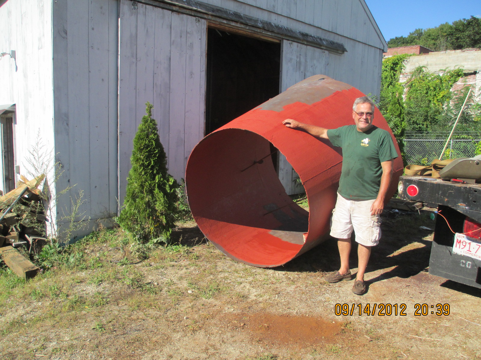
We are in
the process of priming the draft tube.
We could
not find all of the pieces of the skirt. We are having them
fabricated and will weld them on afterwards.
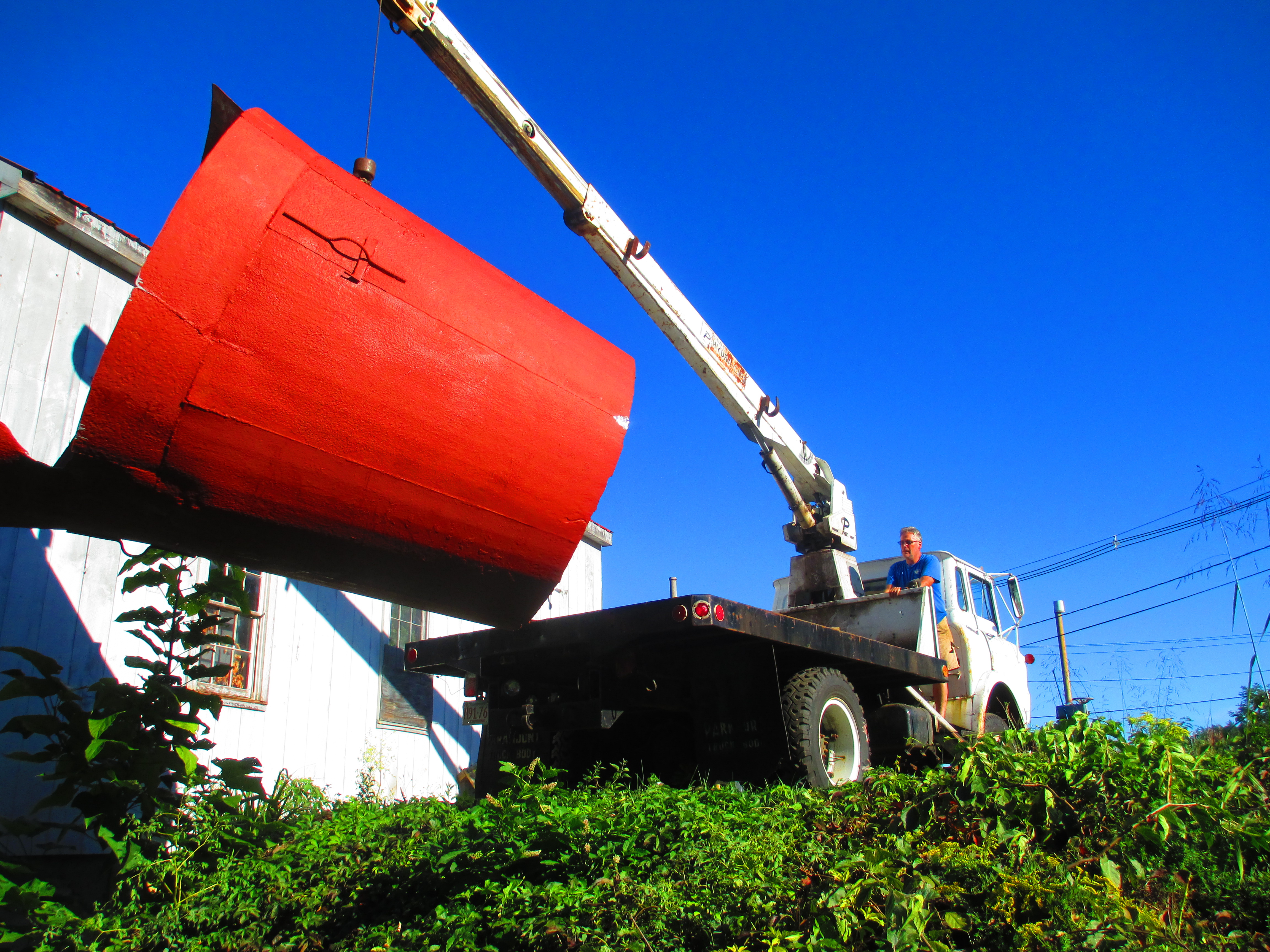
The draft
tube is being lowered into the tailrace.
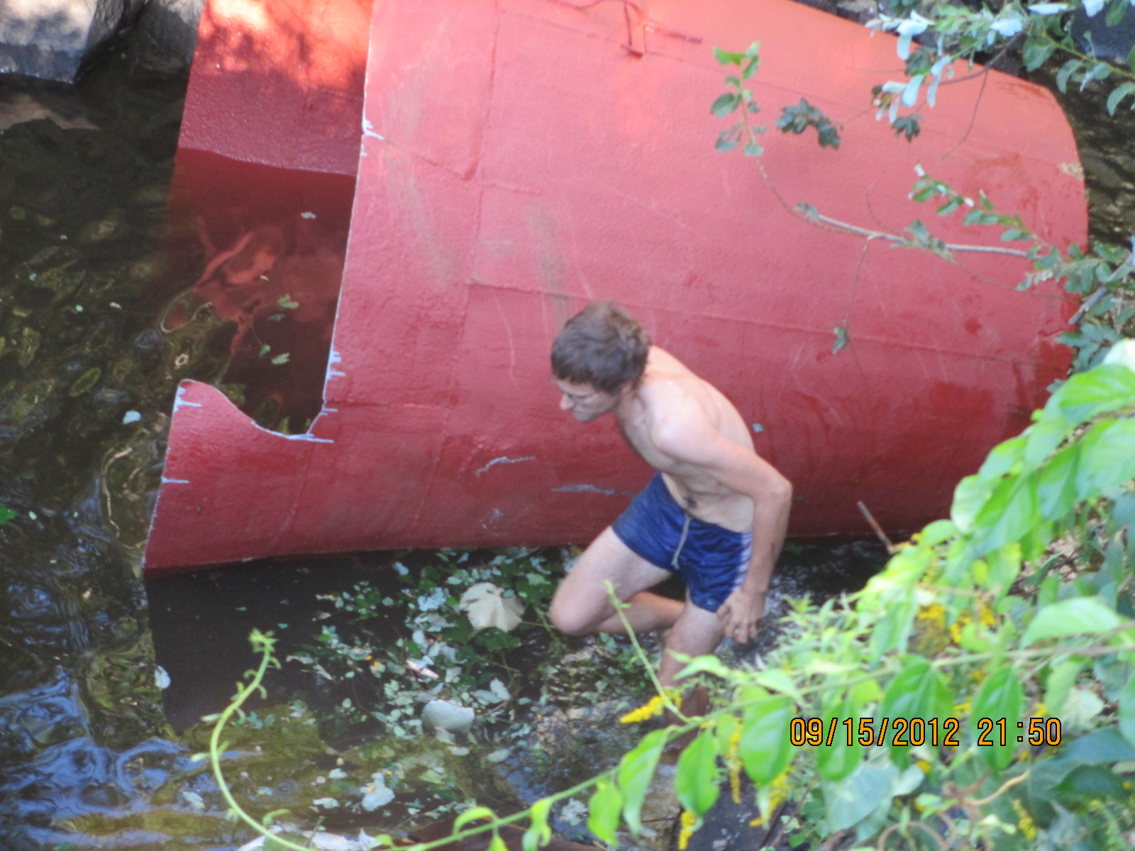
Will is
retrieving the rigging off of the draft tube. Subsequently, my
wife Karen ran the crane. Will attached a snatch block to the
back of the discharge pit and reeved the crane cable through the
snatch block back to a plate hook clamped to the draft tube.
While Karen pulled on the cable, Will guided the draft tube
beneath the power house.
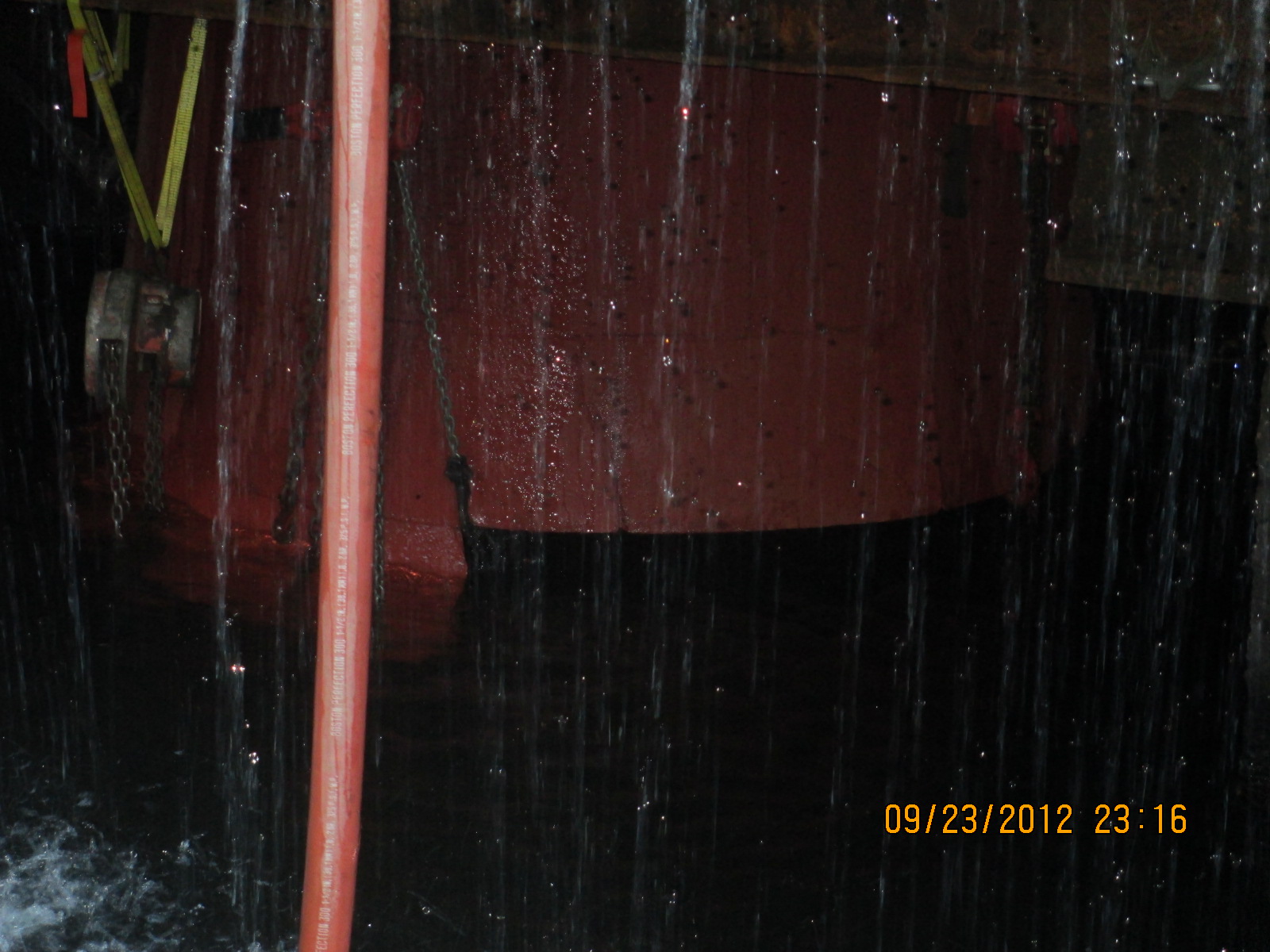
Here we
have sucked the draft tube up to the steel throat liner. We had
to slice the draft tube longitudinally several times to lift the
cone vertically in the conical hole. We welded in staging and
installed a blower system for fresh air. Will spent another week
inside the draft tube welding the seams back together and
welding the upper circumference of the draft tube to the steel
throat piece.
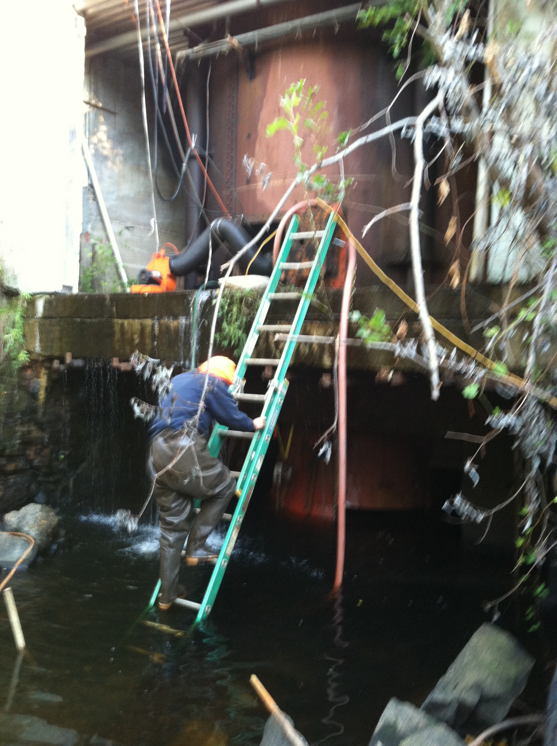
Here is a
photo of Will ready to weld inside the draft tube. He has to
climb the ladder and squeeze threw the pressure case man hole.
He than squeezes threw the draft tube manhole, grabs onto the
runner and swings down onto the staging. The blower provides
clean air in Will's face while he welds. We opened the wicket
gates and the welding fumes are sucked up the penstock and up
the vacuum vent pipe like a chimney.
January
16th, 2013, added the following sidebars:
Added,
"Erection and Alignment of Vertical Waterwheel Generator Plants"
by R. O. Standing, Niagara Falls, Ontario, January 15th, 1951.
Added,
"Hydraulic Turbine and Governour Field Erection Information",
NEMA Hydraulic Turbine Section, June 12th, 1953
Added,
"Generator Shaft Design Calculation", Olav Hodtvedt, September
20th, 1985.
December
30th, 2012
Added
sidebar: Admitting Air to Turbine Runners Improves Efficiency,
S. Logan Kerr |