 GREEN
GREEN
AND
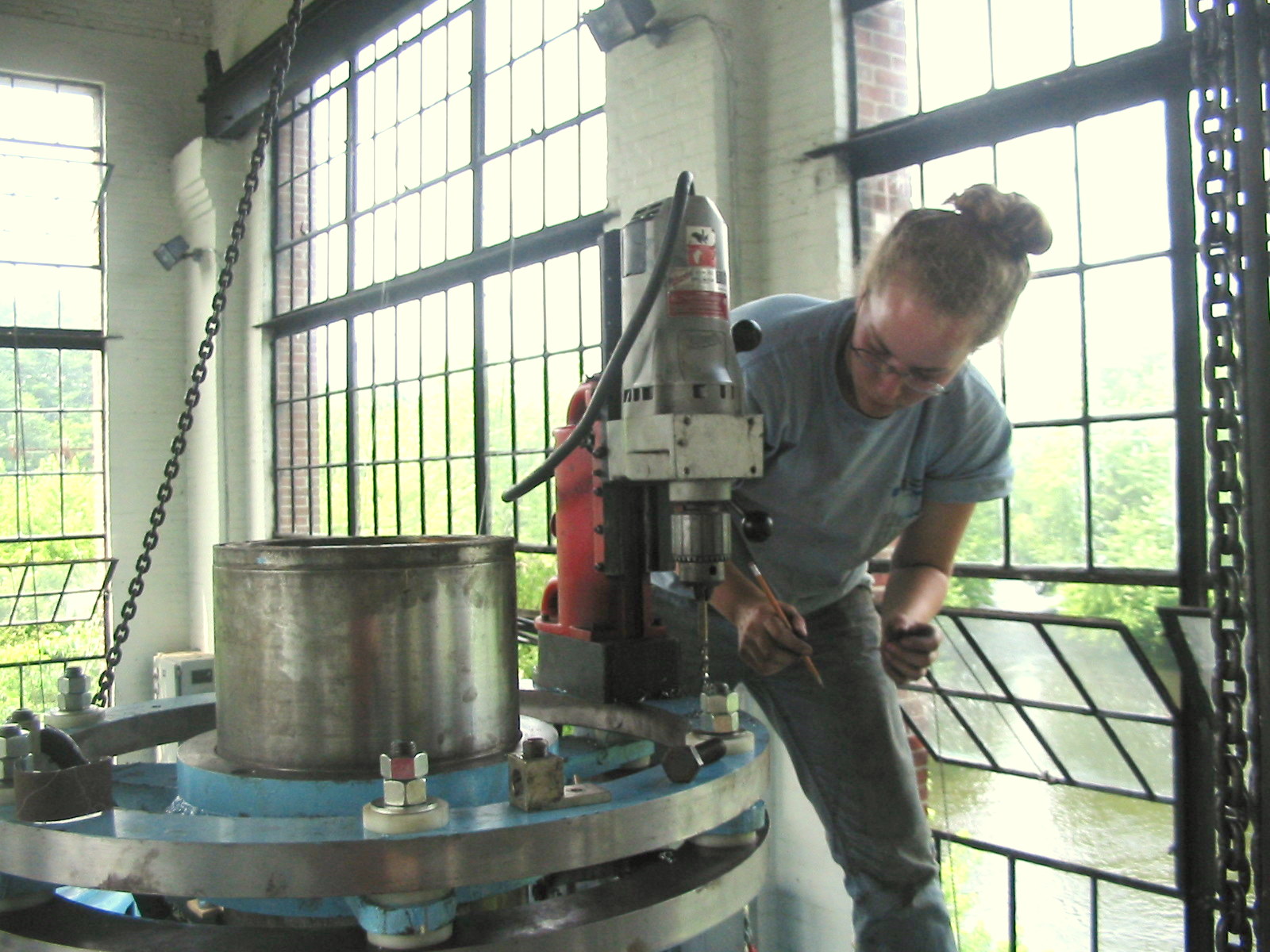
CLEAN
POWER
French River Land Company's Website!
|
AND CLEAN POWER French River Land Company's Website!
|
|
French
River Land Company's Home Page!
Rebuilding 120" Niles Boring Mill HYDROELECTRIC SITES: Anasagunticook Lake Dam Replacement- C.Fay & W.Fay Appleton Wisconsin Anniversary Senor Bonifettis' sites in Chile Turners Falls Generator Rewind USEFUL ENGINEERING: Admitting Air to Turbine Runners Improves Efficiency, S. Logan Kerr Air Admission to Hydro Runners, David Cox, USCOE, Kerr Dam Archimedian Screw Pump Handbook- Gerhard Nagel A Self-Adjusting Spring Bed Bearing- Henry G. Reist ASME 1646 The Banki Water Turbine Mockmoore and Merryfield Bearing Currents: Their Origin and Prevention C. T. Pearce Bishops Method- STABGM Program Blade Pitting- Boving LTD 1930 Cavitation- Accelerated Research, Allis Chalmers Research Cavitation & Vibration of a Draft Tube Cavitation- Prevention & Reduction, Allis Chalmers Research Causes & Effects of Cavitation in Hydraulic Turbines Chain Turbine by: Nguyen Minh Duy Chain Turbine Mechanics- Discussions with Duy Characteristics of Modern Hydraulic Turbines-Chester Larner Comparative Tests On Experimental Draft Tubes- C M Allen & I A Winter 1923 Design of an Overshot Waterwheel (by Carl Weidner) Design of Small Water Turbines for Farm and Small Communities Design of the runner of a Kaplan turbine for small hydroelectric power plants: Timo Flaspöhler Draft Tubes of Hydro-Electric Stations by M. F. Gubin Ejection into Tailraces of Hydropower Plants: S. M. Slisskii Erection & Alignment of Vertical Waterwheel Generator Units-R.O. Standing Evolution of Hydraulic Prime Movers-Byron McCoy Fall Increaser Herschel Venturi Tube Fall Increaser Moody Ejector Turbine Fall Increaser Hydraulic Jump Apron Generator Shaft Design Calculation- Olav Hodtvedt Governor Theory for the Plant Operator Graphics of Water Wheels- William Fox Hydraulic Motors- M. Bresse & F. A. Mahan 1869 Hydraulic Power Transmission by Compressed Air Hydraulic Rams their Principals and Construction by J. Wright Clarke Hydraulic Turbine and Governor Field Erection Information Hydraulic Turbines- Robert Long Daugherty Hydraulic Turbines by Arnold Pfau Hydraulic Turbines Gelpke & Van Cleve Hydrokinetic Energy in Massachusetts, William D. B. Fay HYDROTURBINES DESIGN AND CONSTRUCTION N. N. KOVALEV Impulse Turbines by Ely Hutchinson Interference fitting a large runner shaft Kaplan Blade Design NACA Air Foil- Report No. 460 Kaplan Blade Design NACA Air Foil- Report No. 628 Kaplan Design Marko Kogovsek.xls A Laboratory Study to Improve the Efficiency of Crossflow Turbines- N. Aziz & V. Desai Loading Vertical Thrust Bearings R. C. Johnson Low Head Hydroplants, Emil Mosonyi Meggering Earth Resistance Motors as Generators for Microhydro, Nigel Smith Operation & Maintenance of Hydro-Generators Out Gassing of Cross Flow Turbines Parallel Operation of Turbines Analysis Powerhouse Design- Miniwatt Hydro Rack Design-Chicopee-Olav Hotvedt Rack Design- Hydraulic Institue of Munich Rack Design-Flow Induced Vibrations Selecting Hydraulic Reaction Turbines BUREC Snows Improved Water Wheel Governor Standard for Hydraulic Turbine and Generator Shaft Couplings and Shaft Runout Tolerances Stoplog Structure Design Calculation Stress Analysis of Hydraulic Turbine Parts, BUREC- F.O. Ruud Some Fluid Flow Characteristics of a Cross Flow Type Hydraulic Turbine- Durgin & Fay Technology of Heavy Electric Machine Building HydroGenerators Tenth Census of the US, 1880, Water Power of the US, Part I- Professor Trowbridge Tenth Census of the US, 1880, Water Power of the US, Part II- Professor Trowbridge Tests on a Kaplan Hydraulic Turbine Theoretical Conditions Related to an Open Channel Flow Linear Turbine- Ishida & Service Theory of Turbines- De Volson Wood Tidal Energy for Hydroelectric Power Plants by L. B. Bernshtein Treatise relative to the Testing of Water-Wheels and Machinery, James Emerson 1879 Trash Rack Differential Equations 2L/3 Trashrack Differential Equations General Solution f(x) Turbine Water-Wheel Tests- Robert Horton Turgo, A High Speed Impulse Turbine- Paul Wilson Water Hammer and Surge Tanks G. V. Aronovich Water Hammer-Lorenzo Allievi-Text Water Hammer-Lorenzo Allievi-Figures Water Hammer-ASME Symposium 1933 Waterpower Engineering-Daniel Webster Mead Water Turbines Contributions to Their Study, Computation and Design-S.J. Zowski TRADE CATALOUGES: ASEA- Bearings for Large Vertical Hydro-Electric Machines Bradway Turbine (progressive gate) Christiana Machine (register gate) Electric Machinery Company (EM) General Electric- Standard Specifications for Hydro Thrust Bearings and Runners Head Gate Hoists- S. Morgan Smith J & W Jolly (cylinder gate) Lombard Direct-Connected Oil Pressure Governors Bulletin N0. 113 October 1st, 1912 Lombard Governor Company Type T Instruction Book Lombard Governors for Waterwheels and Steam Engines-1902 Lombard Water Wheel Governors Catalouge 26 Ridgway Perfection Water-Wheel Vertical Shaft Water Wheel Driven Generators- General Electric Westinghouse Small Vertical Waterwheel-Driven A-C Generators, July 1944
Links:
Small Turbine Manufacturers Websites: www.waterturbine.com
|
Previous Pictures Three Web Page I posted too many photographs on the website. It was becoming very slow to load. I moved some of the previously posted photographs here.
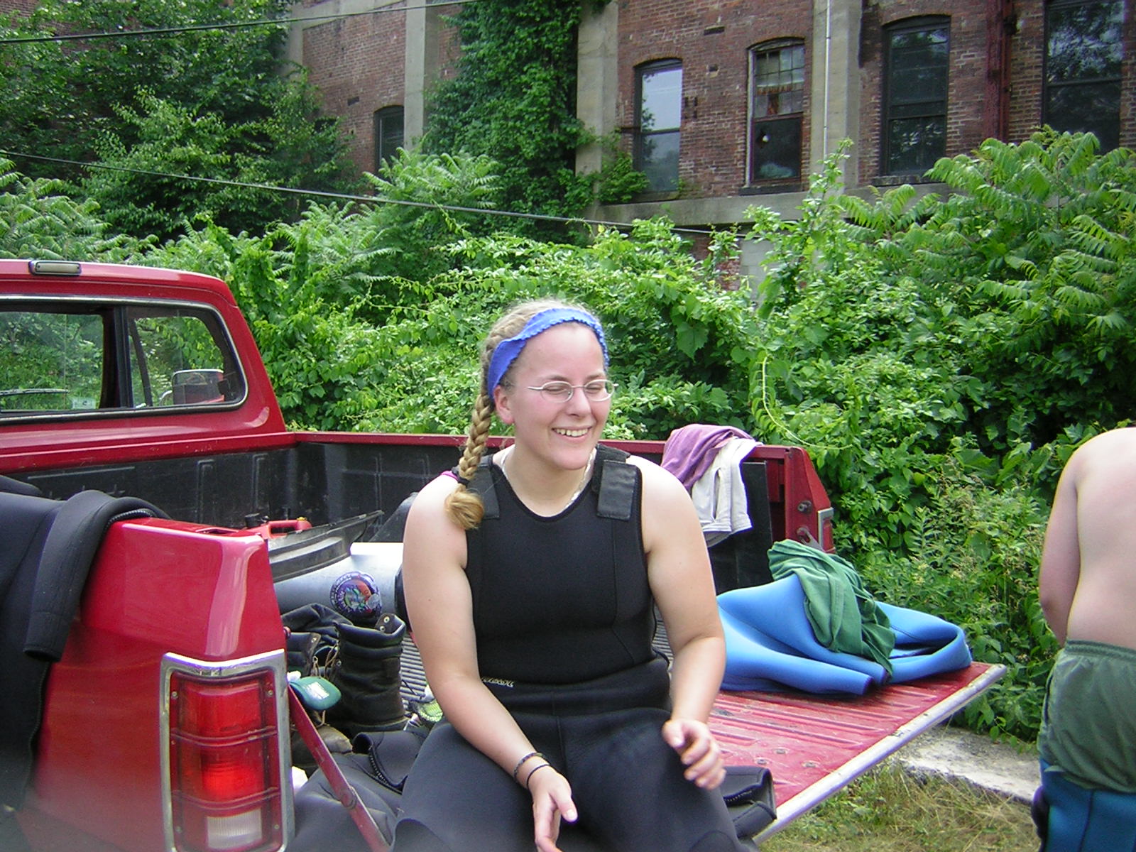
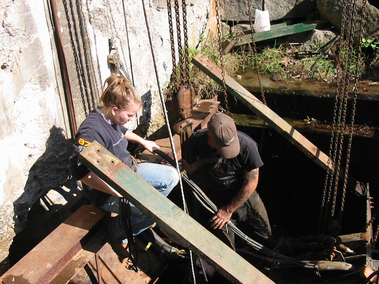
Celesty and Will getting ready to dive on the forebay at Woronoco HEP. Sand had built up in front of the west rack and the trash rake would not descend to the sill. They cleaned out the sand.
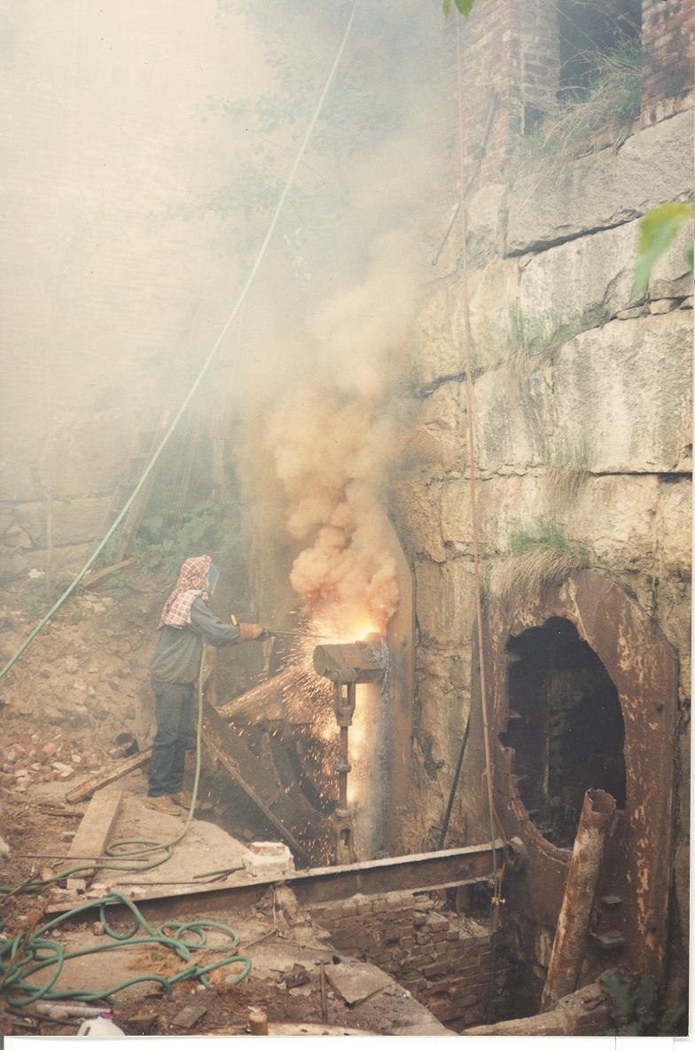
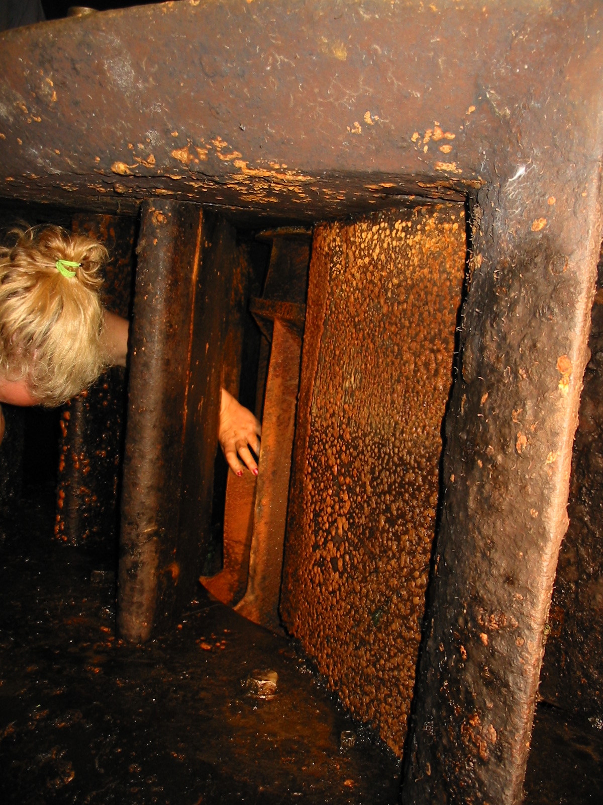
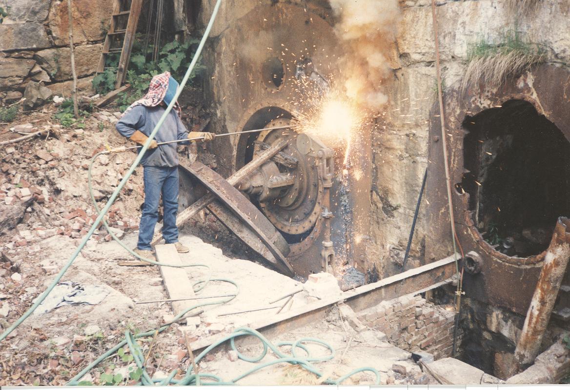
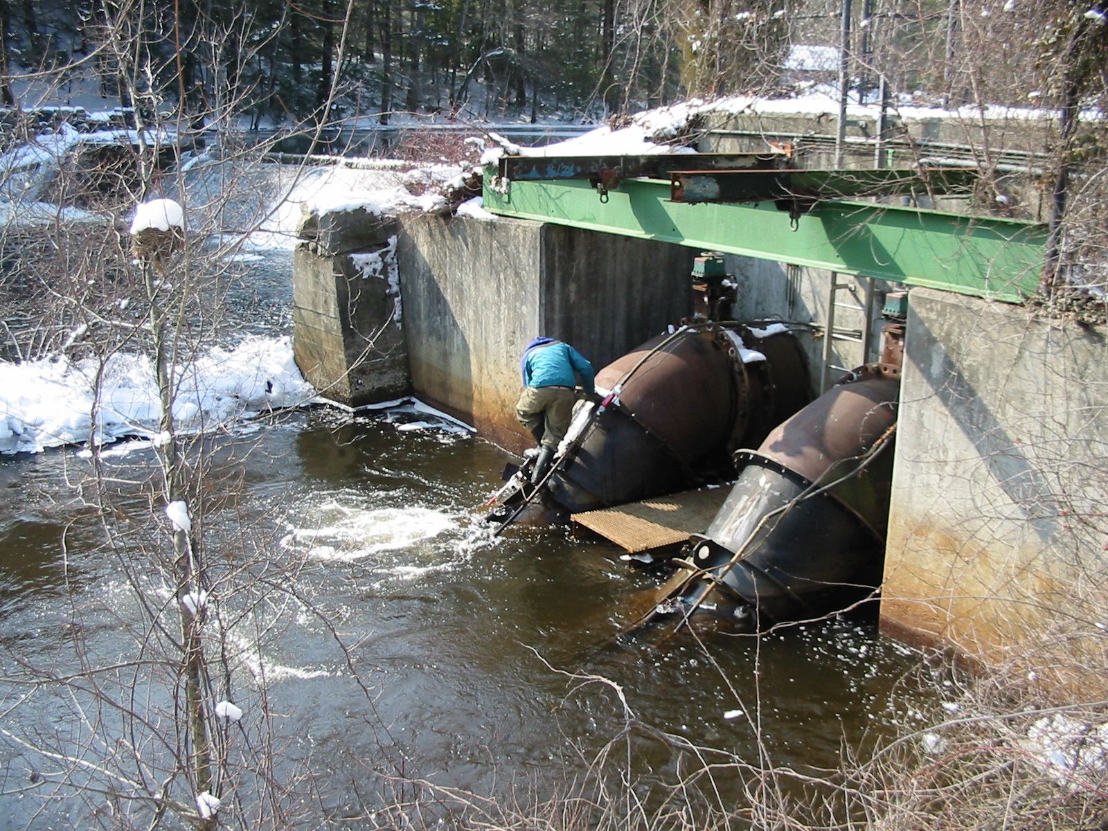
Removing the Rodney Hunt turbines at Livermore Falls, N.H. Bill Fay is using thermite bars to burn the 3 inch thick cast iron head covers at Livermore Falls. Here the cold of outer space (liquid oxygen at minus 297 deg F) is feeding the fires of hell (OxyAcetylene burns steel at 2500 deg F, the surface temperature of the sun is 16,000 deg F. The tip of the thermite bar runs 8,000 deg F). The thermite bars are consumed like a punk stick. As they burn down the 8,000 deg F gets very close to your hands!! Once they are ignited, we could carve our initials in solid granite. (Livermore Falls<<click here for Livermore Falls)
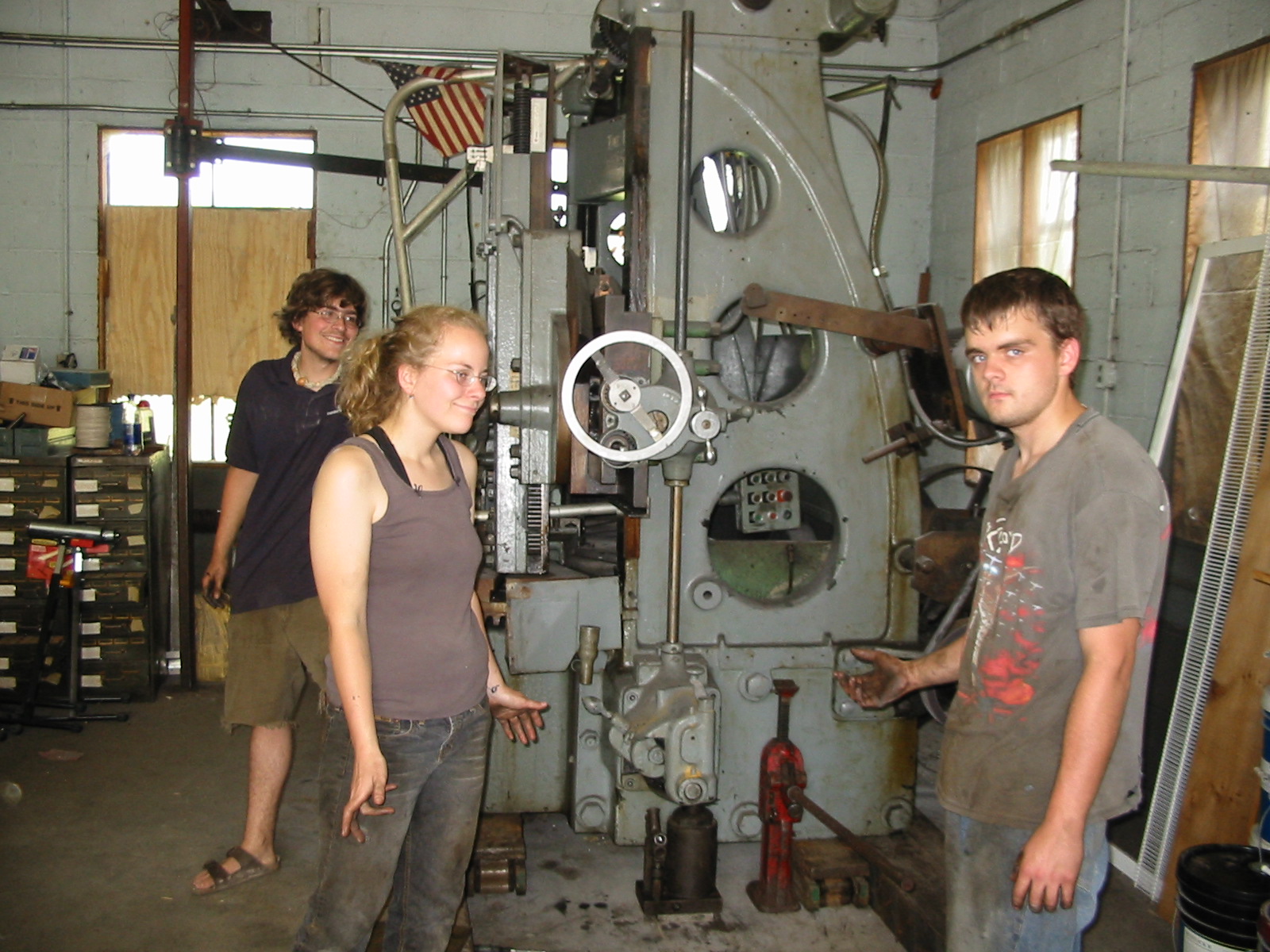
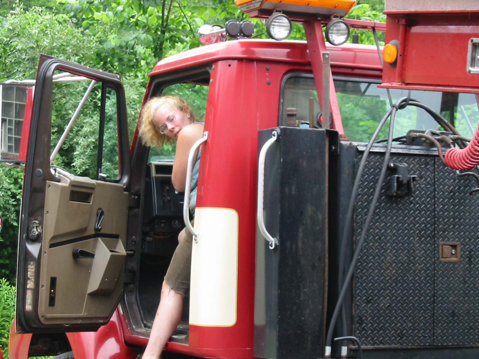
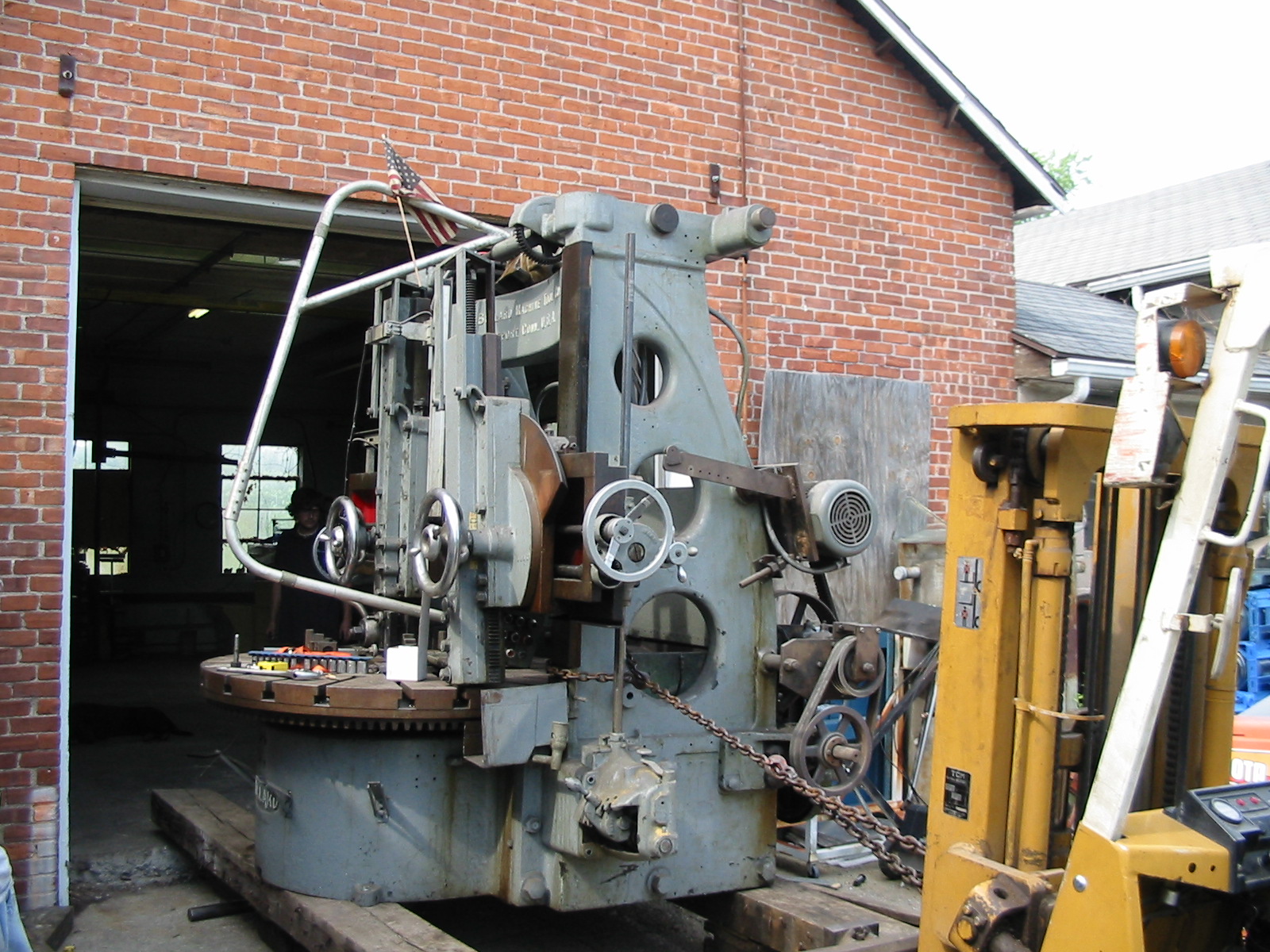
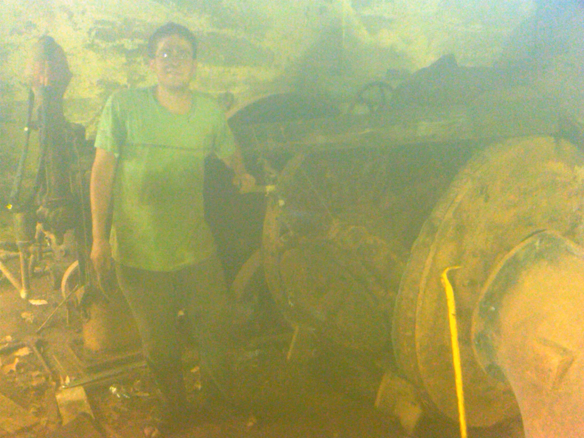
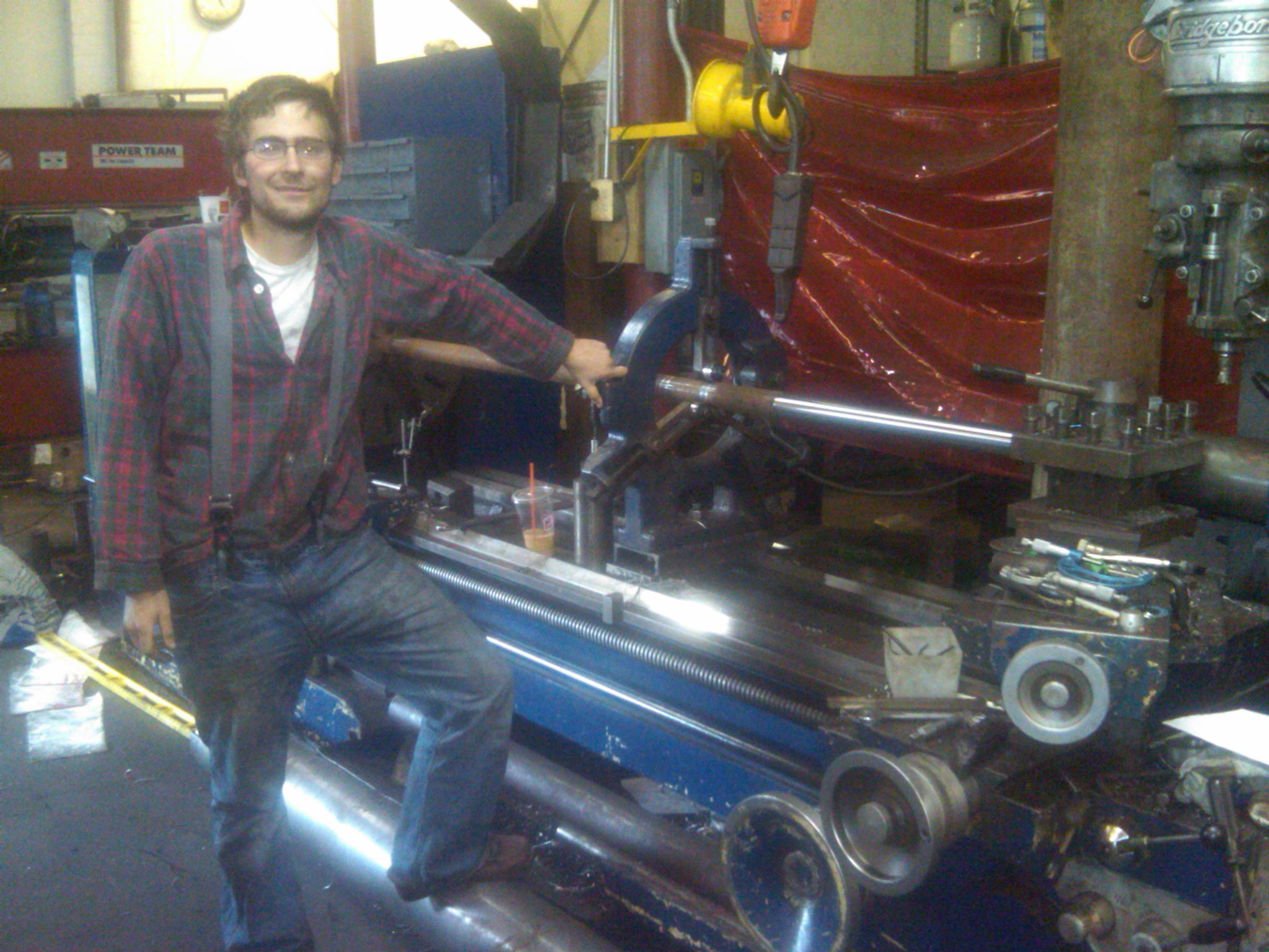
I had been searching for a 60 inch Bullard for several years. I could afford neither the $60,000 price tag, that they were going for, nor the $10,000 trucking charge. Finally I found this one, on e-bay, two towns over from the shop for $3500 that included the flag and digital read out!!! Here Will, Celesty and Ronnie have jacked it up and placed it onto caterpillar machinery rollers in order to ship it back to the shop. We were looking for a service manual. The folks who are supplying parts for Bullards told us to look on the cross slide for a 5 digit serial number that would help them select what manual to send to us. I looked and found only a three digit number. We told the number to the factory rep. He called back and told us our Bullard had left the factory in August of 1902!!! It was the oldest Bullard that he new of that was still being used in a commercial operation. I was very pleased to get it. Will did put on his steel toed boots after this photo was taken. April 11th, 2009, added scanned textbook, Hydraulic Motors by M. Bresse as translated by F. A. Mahan, July 1869. Also added links to Part I and Part II of the 1880 US Census, Water Powers of the United States. Got up at 5:00 AM cleaned both sides of River Road of all trash from bridge to abandoned house. Got Collin's trash rake and swept beer bottles and trash from sun turtle's little pond. April 2nd, 2009, added scanned textbook, Hydraulic Turbines by Victor Gelpke and A. H. Van Cleve March 29th, 2009, added scanned text book, Theory of Turbines by De Volson Wood, Graphics of Water Wheels by William Fox and Standard for Hydraulic Turbine and Generator Shaft Couplings and Shaft Runout Tolerances. March 23rd, 2009, added Characteristics of Modern Turbines- Chester Larner.
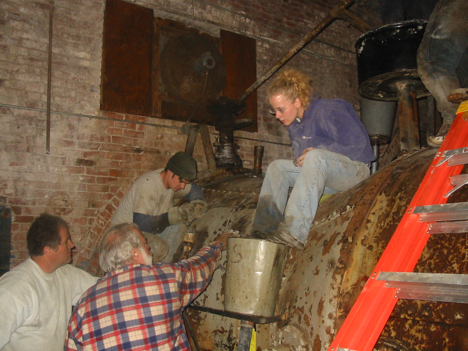
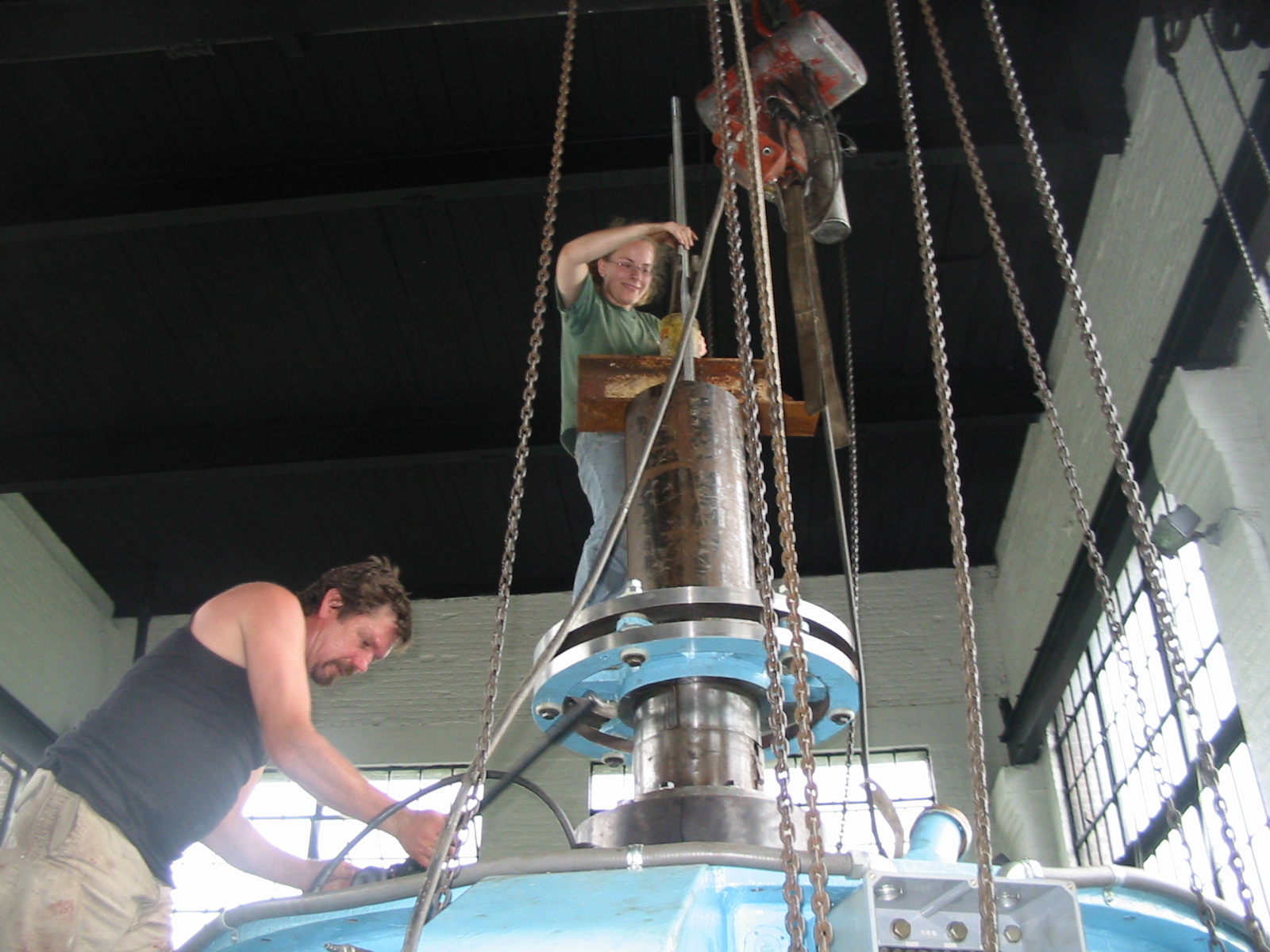
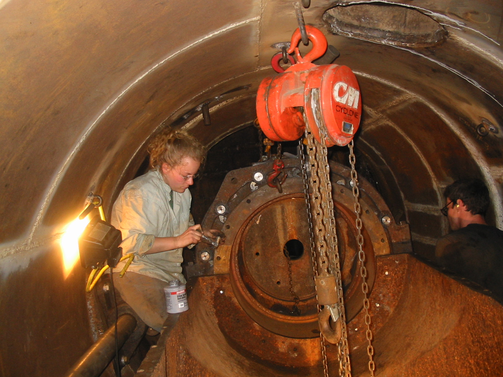
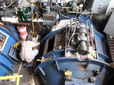
Celesty in action!!!! She is sitting on the Woronoco No. 2 pressure casing. Note the operator for the 72 inch butterfly valve over Mike's head. The crew is grouting the space between the old pressure case and the new steel plate liner. The waste paper basket is welded to a two inch pipe that is inserted between the two layers. See the second bucket located behind Celeste. We mixed the grout, emptied it into the buckets and vibrated it into the cavity.
Celesty in action!!!! She is at the bottom of the Chinese gate case at Brockway Mills. She is moving one of the 75 ton porta-power cylinders. You can see the remains of the Chinese volute case, that needed to be cut out, in order to install the 500 KW, Ossberger Turbine in place. Chris gave me the Dong Fang for cash and a promise to assist him with the concrete removal. The only place to insert the rectangular draft tube was to hammer out a 10 foot wide by 12 foot long by 15 foot deep hole in front of the volute case and breaking out into the roof of the elbow draft tube. We used 30 pound rivet busters to remove the yardage. It took 6 weeks of back breaking work. This plant is currently for sale. Chris has purchased property in Montseratt. He wants to drill obliquely towards the volcano and install several megawatts of vulcan-thermal, steam cycle power!! This is a beautiful plant and has been running superbly!!! He is asking $ 850,000 for the plant. I think it is a steal. If you have a serious interest, please call Chris at: 1-603-499-2350.
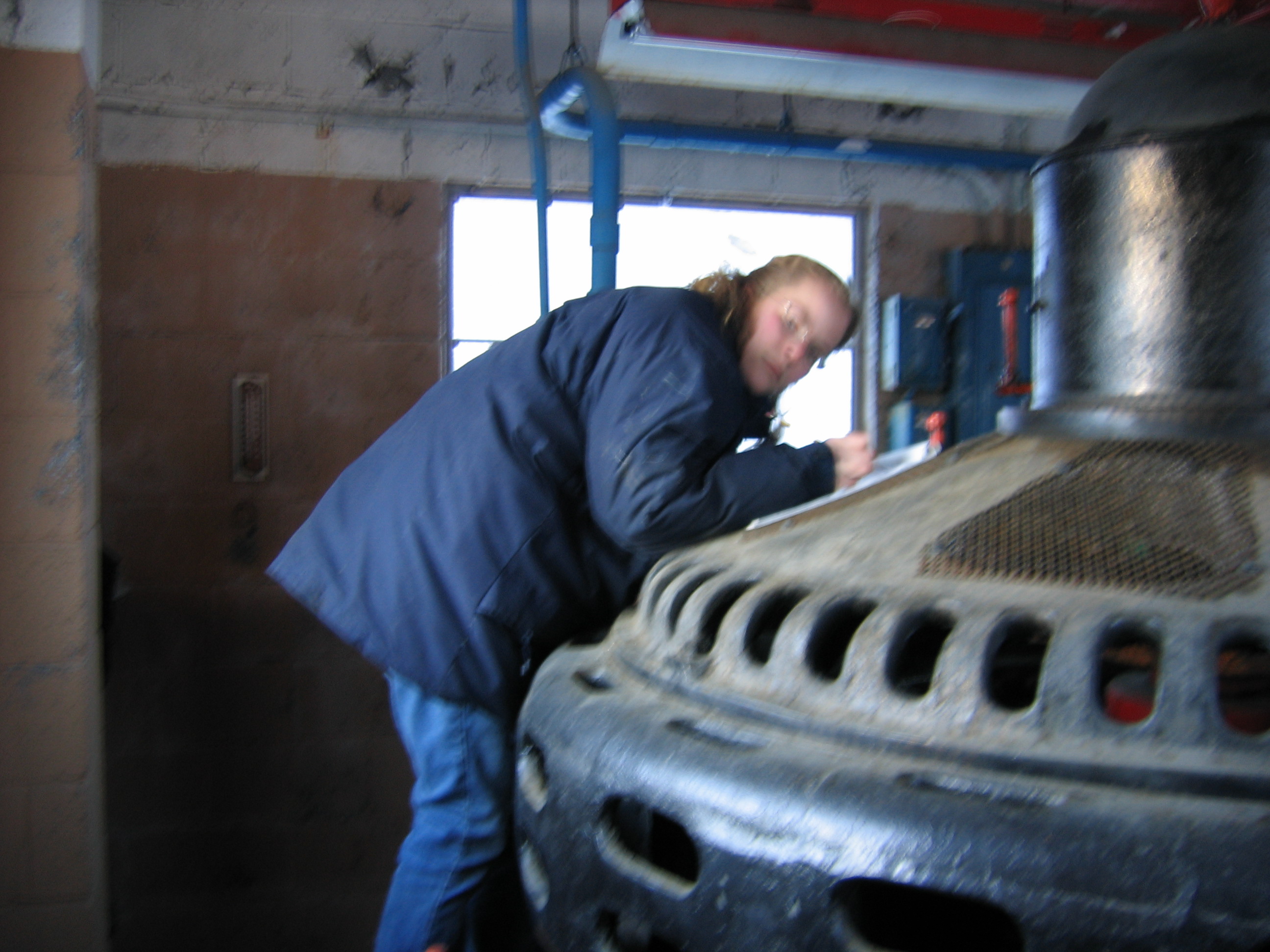
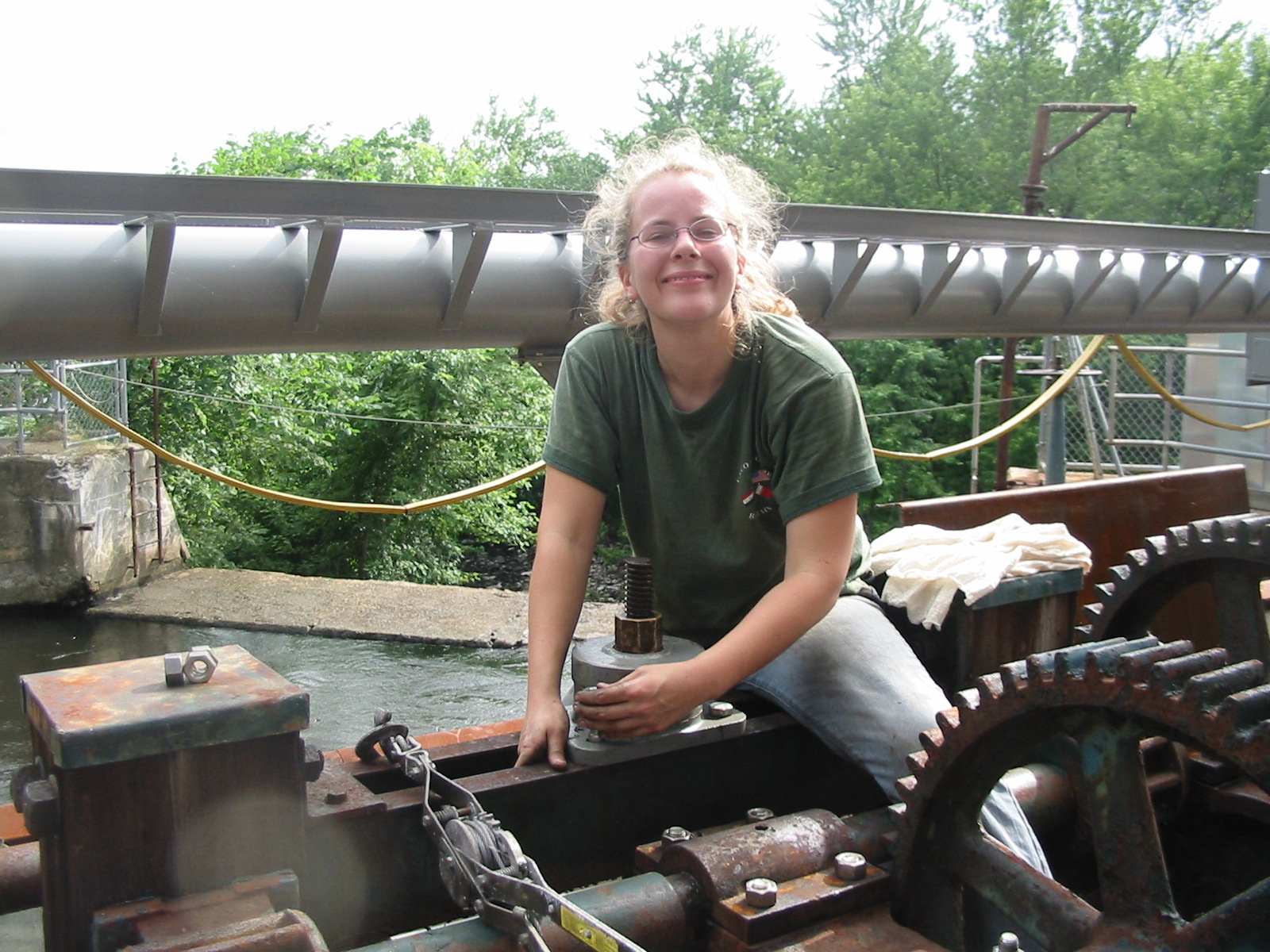
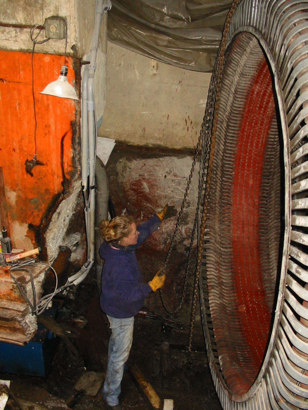
Celesty is inspecting the No. One turbine runner for damage at Pepperell Hydro. Note the chunk of missing runner blade she has discovered. She is holding her hand over the missing piece.
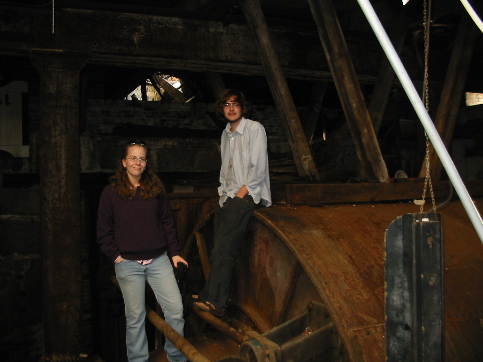
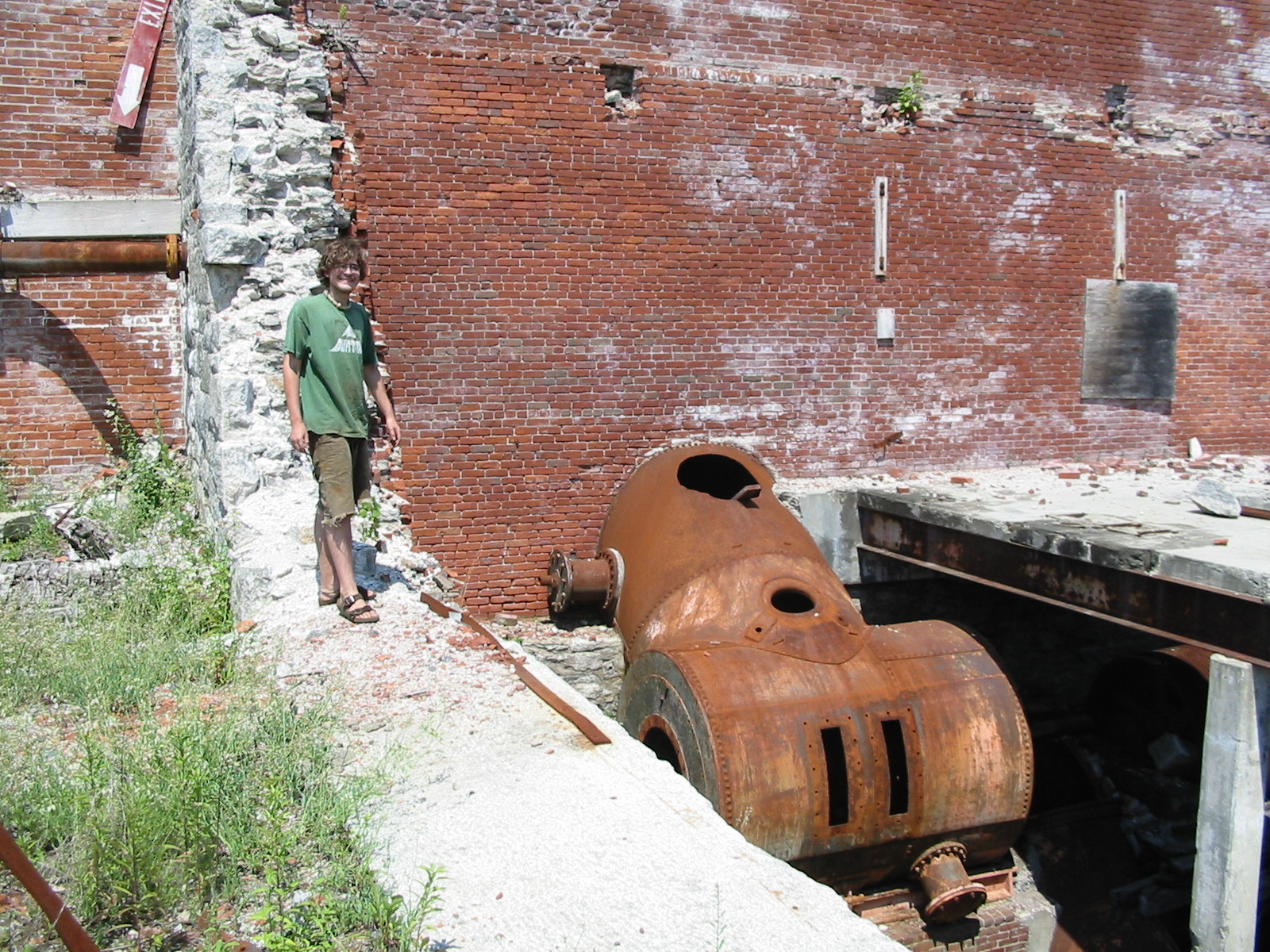
Celesty and Will in the ruins of Appleton Mills in Lowell, MA. Will is sitting on the endbell of the horizontal pressure case. Celesty is straddling one of the cylinder gate operating shafts. Please see the following "You Tube Video" of this site when it was restored in the 1980s by Dave and Luke Wright. http://www.youtube.com/watch?v=efZfa8w7VNg <<< please click March 18th, 2009, Added Operation and Maintenance of Hydro-Generators March 11th, 2009, added brochure, Craig Ridgway, "Perfection" Water-Wheel and Shaft Couplings for Hydroelectric Units March 10th, 2009,
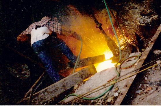
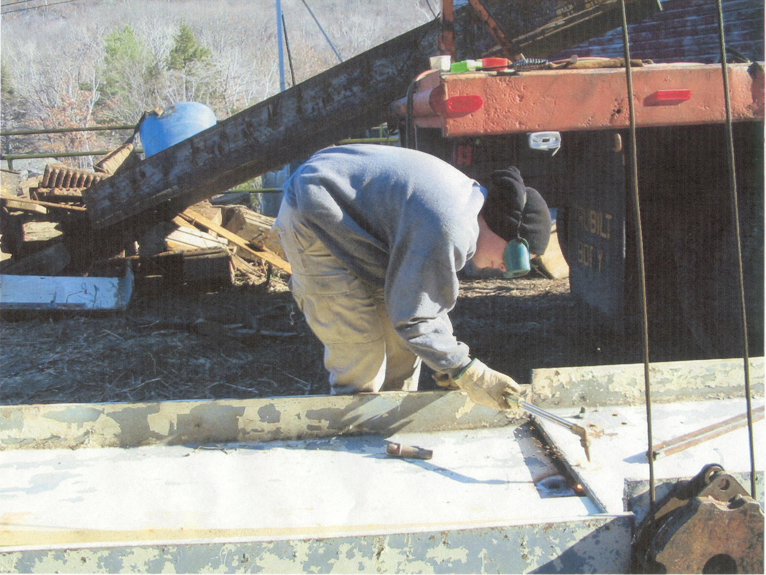
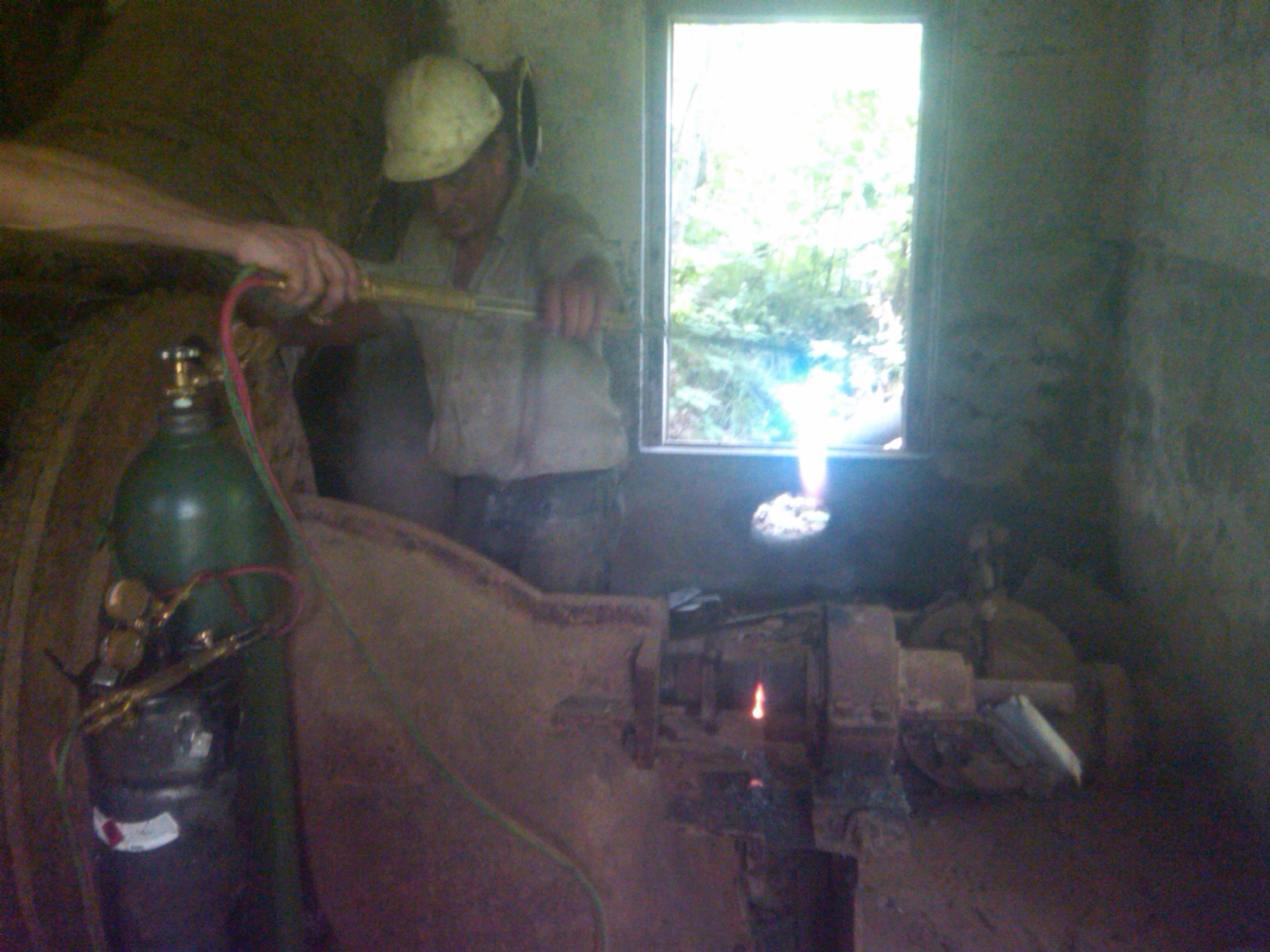
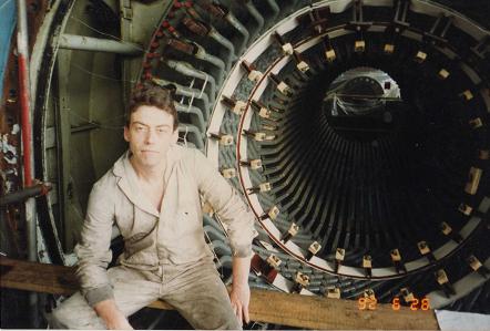
added brochure, Headgates by S. Morgan Smith Company Here, I am using thermite bars to burn the salient pole rotor off of the Westinghouse shaft. We needed the shaft to make our hybrid WestFang Generator. The rotor had sat outside in the weather for so many years, that we were afraid of bending the shaft, if we pressed it out of the flywheel bore. Ronnie Johnson has just lit up the end of the bar with the 30 inch wrecking torch. Once the bar starts to sputter, you crank open the ball valve, on the collet holder and all hell breaks lose!! It never ceases to amaze me how destructive a thermite reaction can be. Kids don't do this at home!!
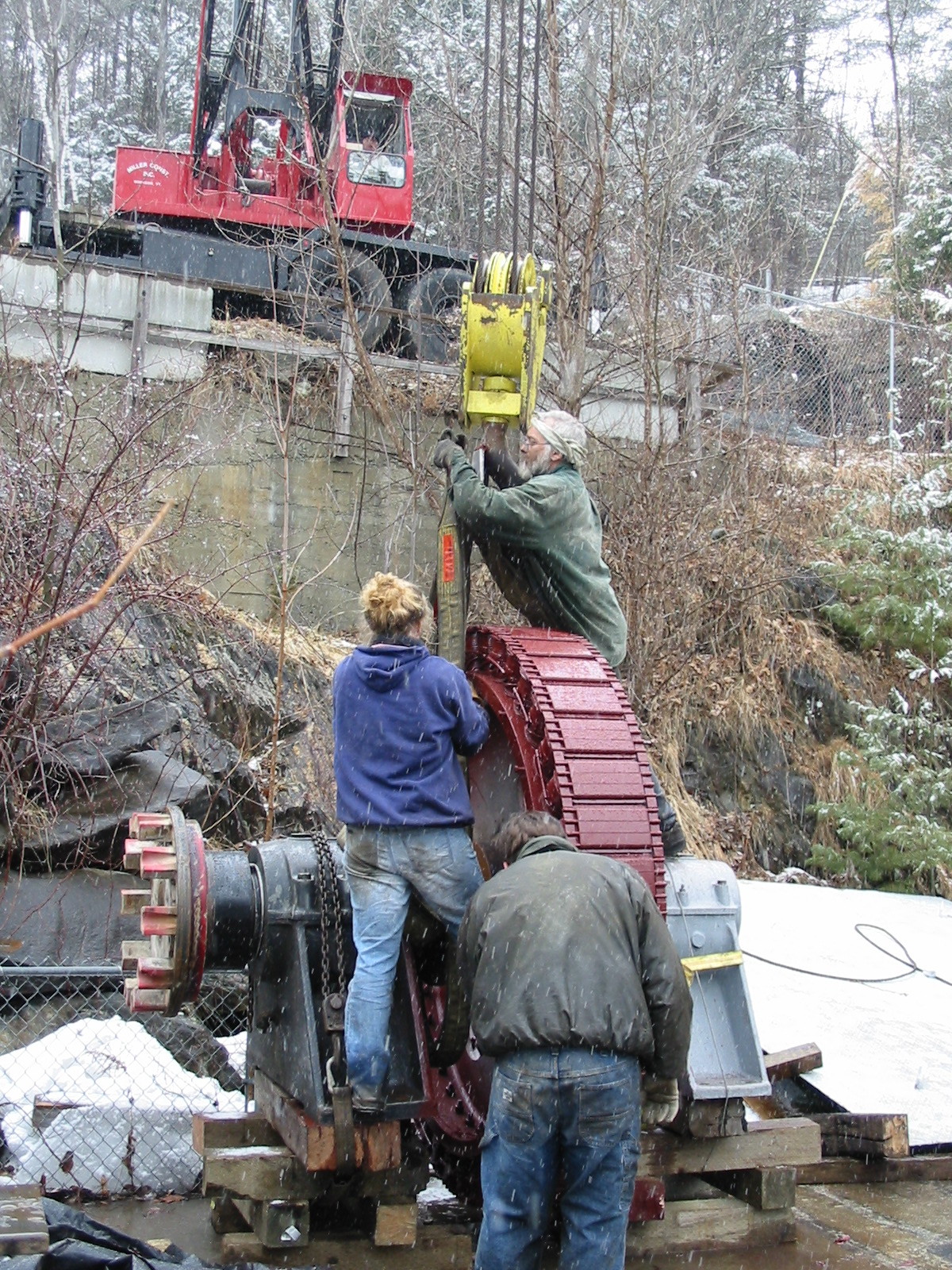
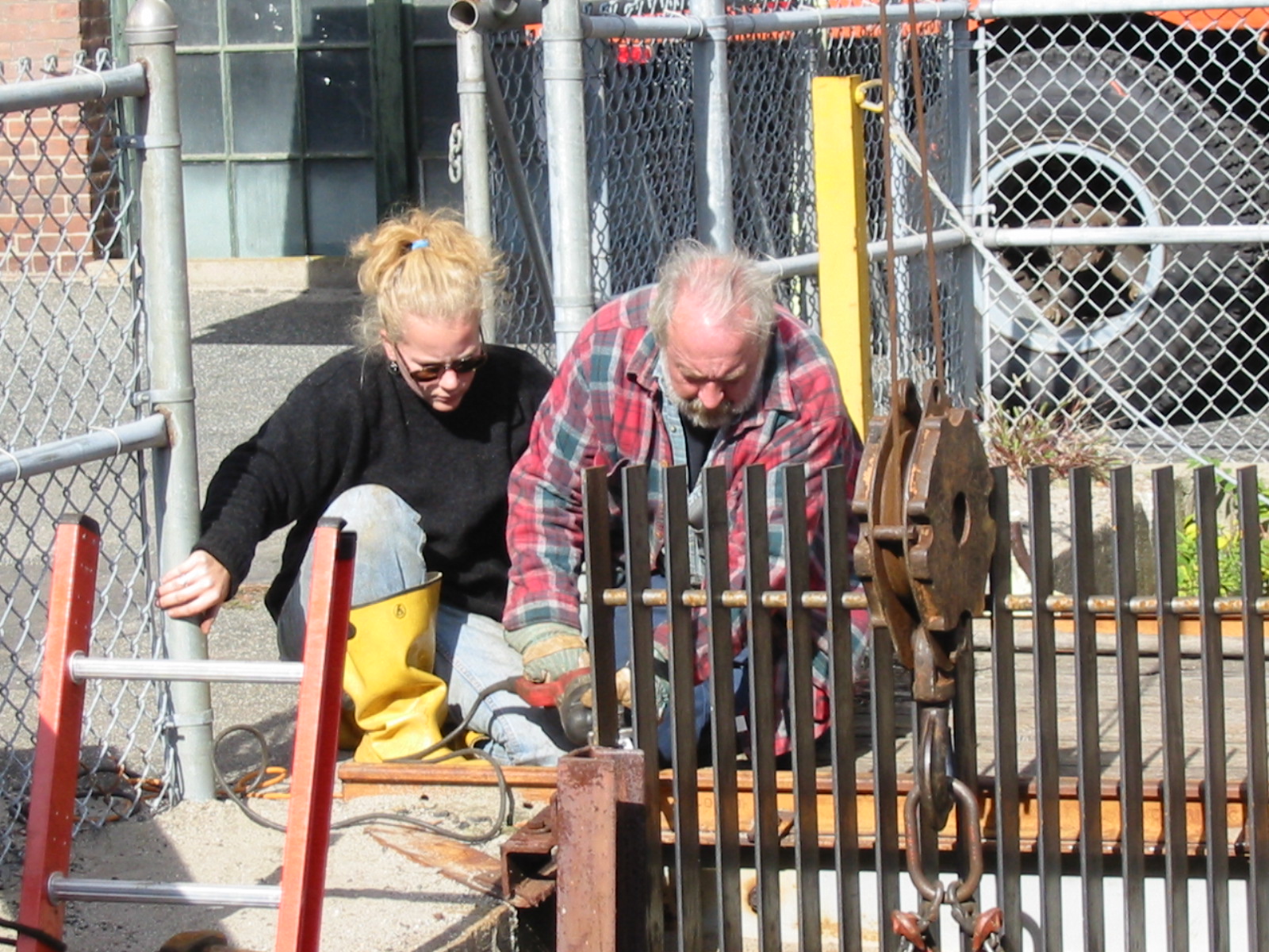
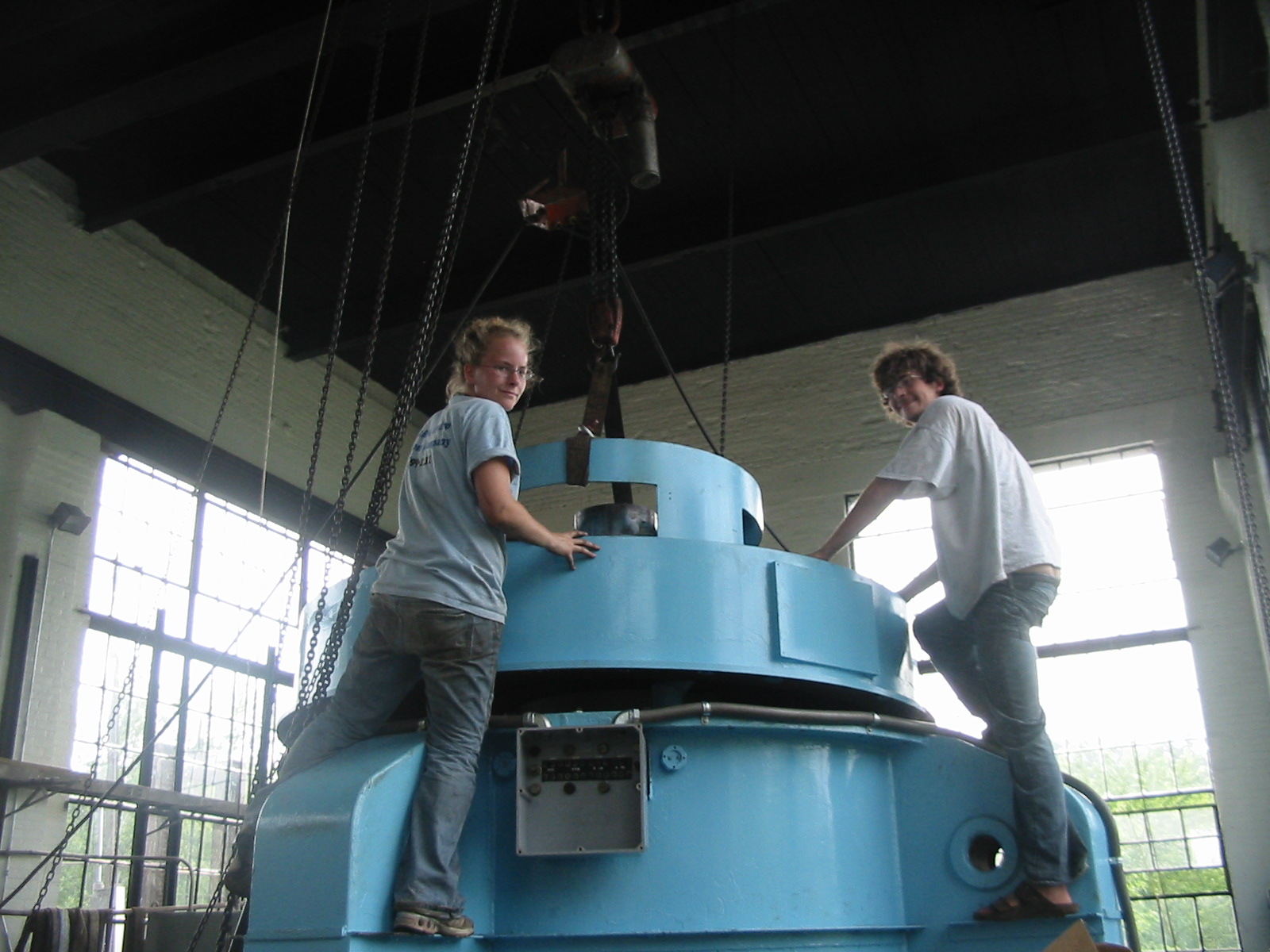
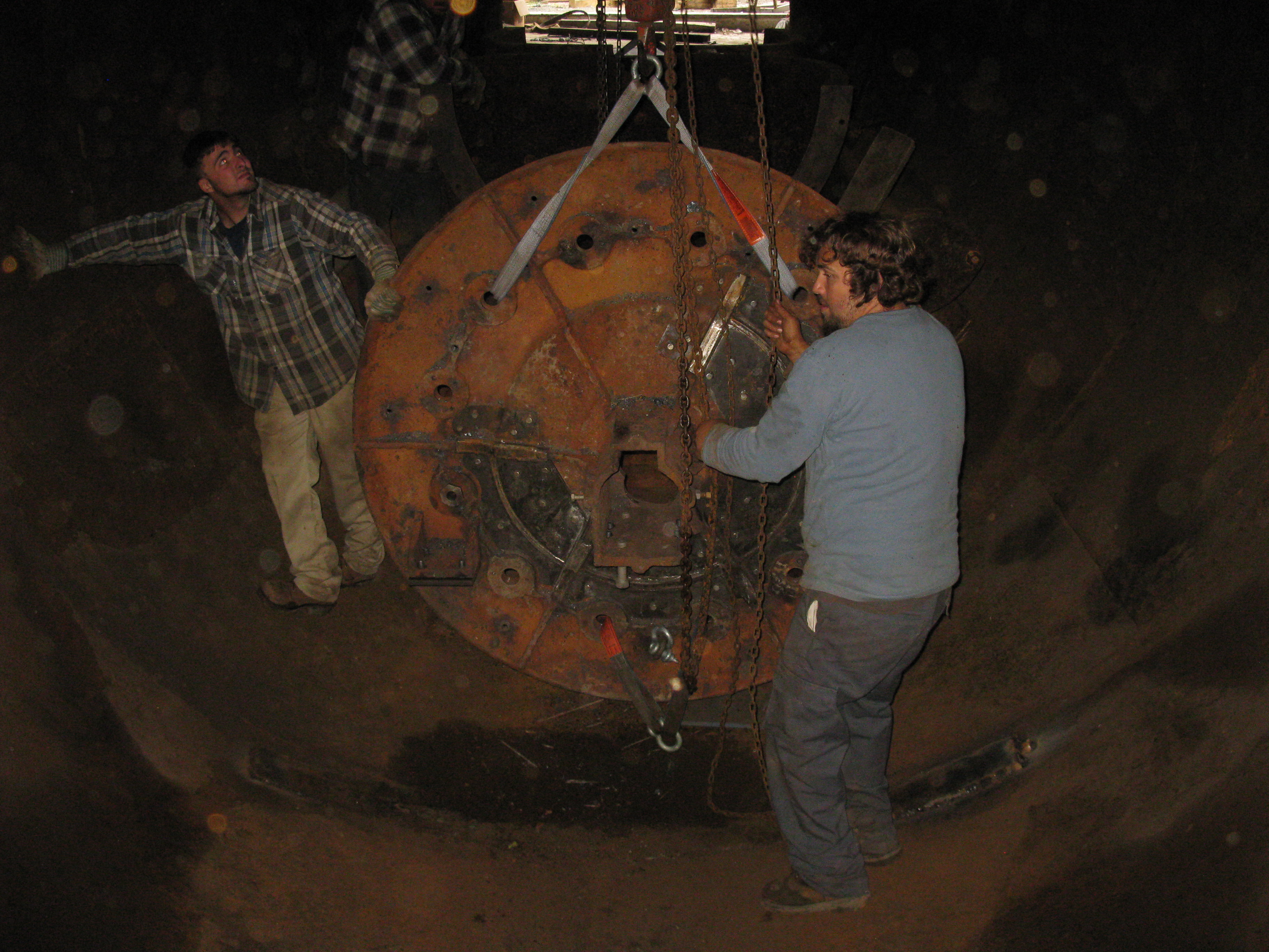
Celesty, Ronnie Johnson and Chris Krueger rigging the Brockway Mills Rotor in anticipation of lowering it into the powerhouse hatch. Look at the size of the crane block compared to Chris' head!!
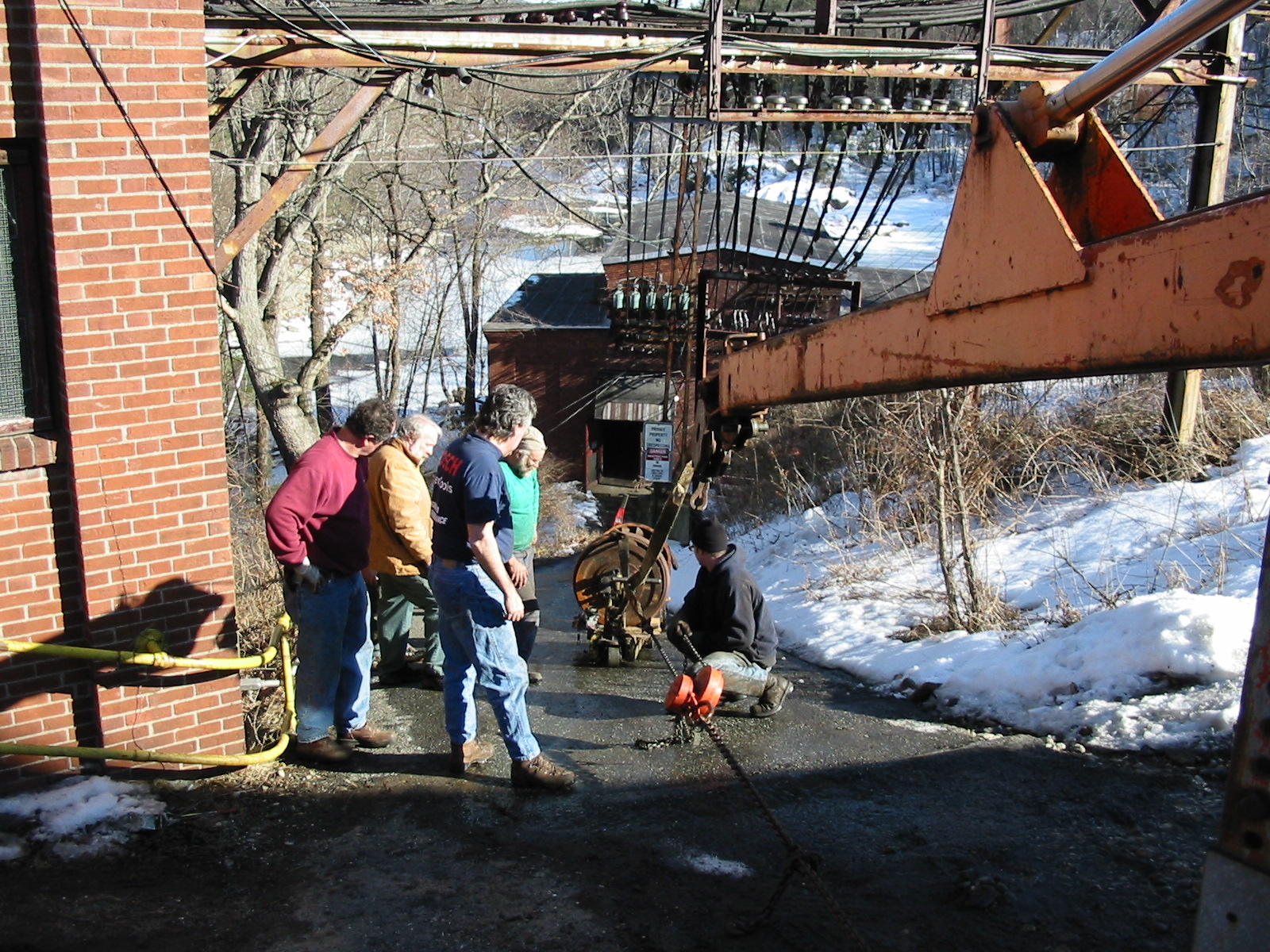
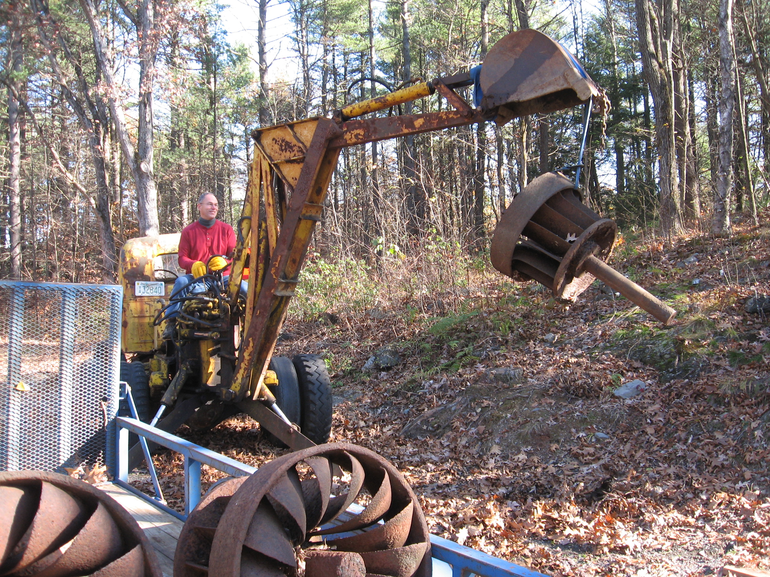
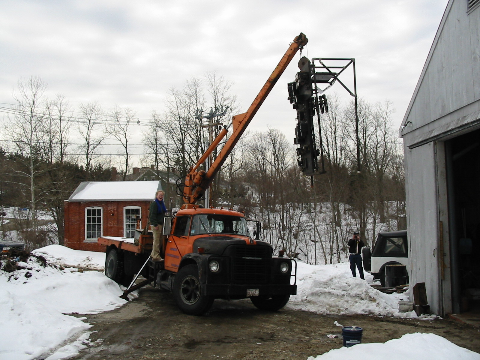
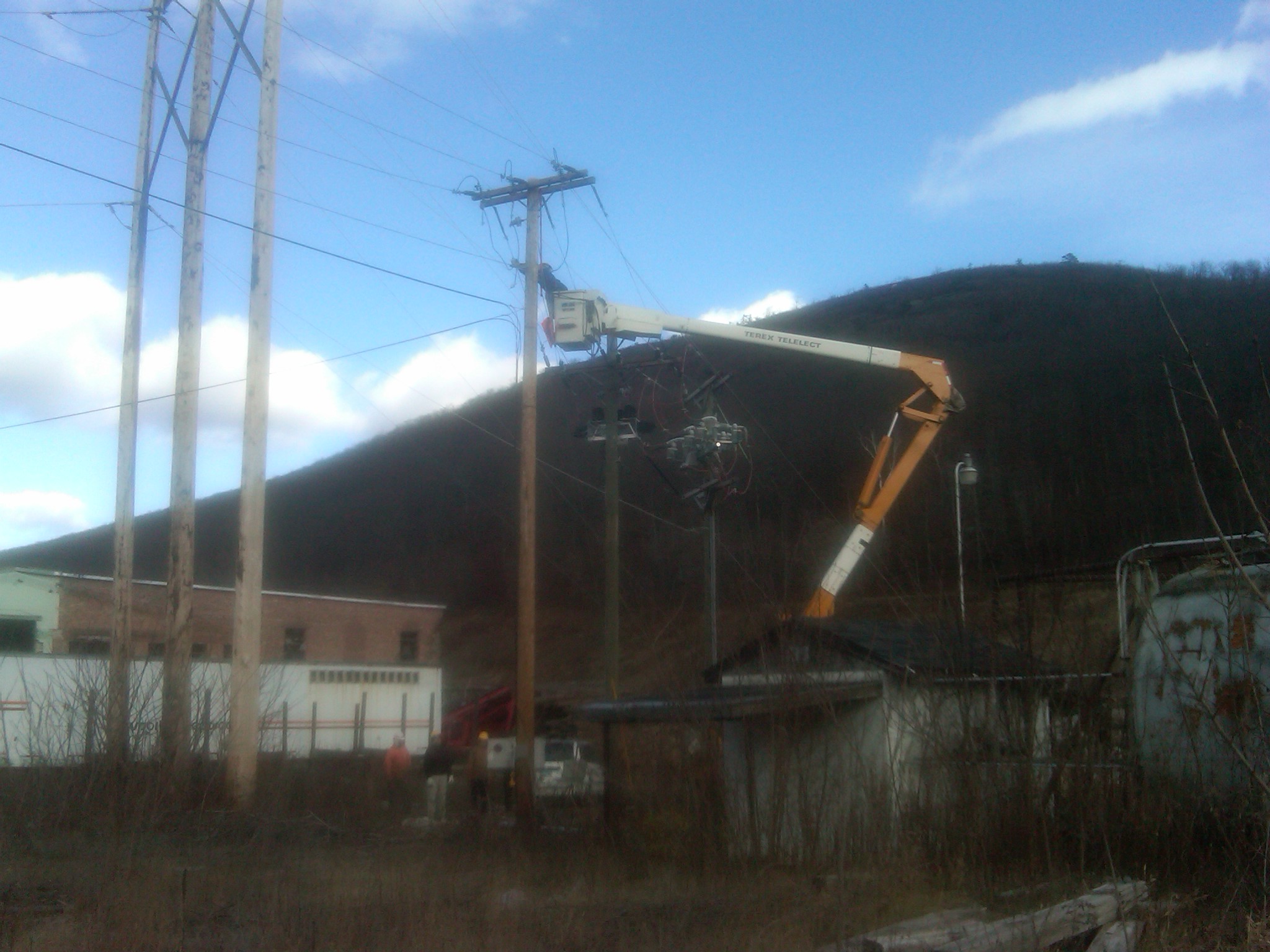
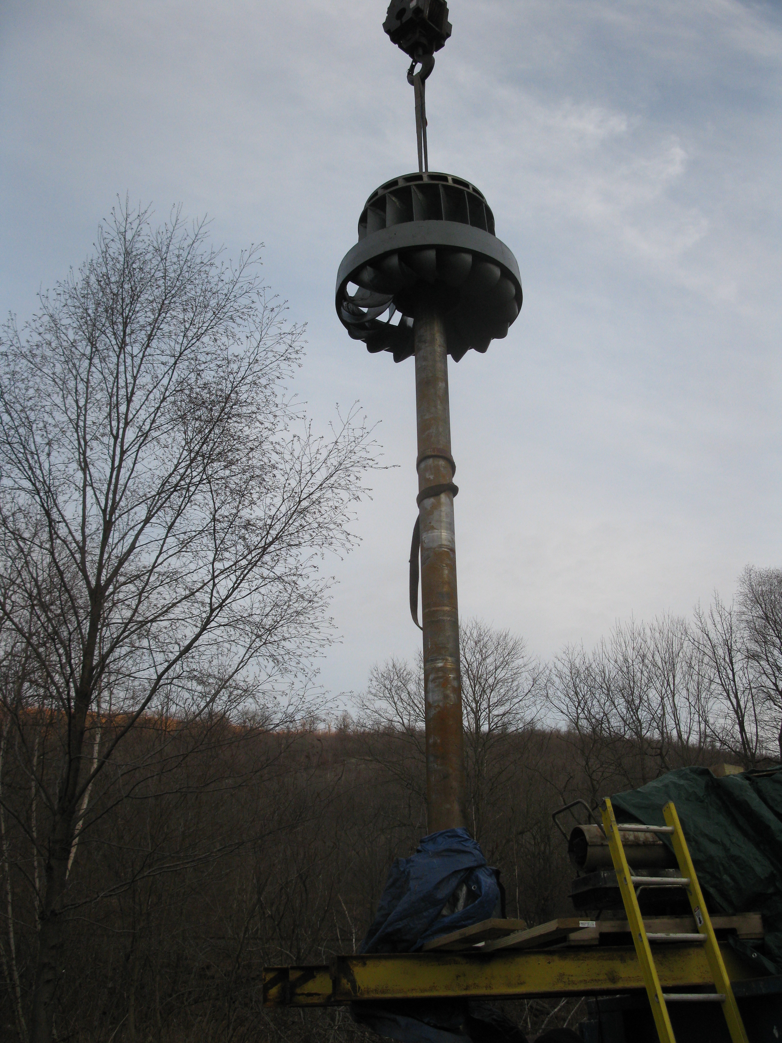
Here's my Celesty operating the cherry picker at one of our sites. She has been operating the crane for years. I get a chuckle out of seeing her bossing around 30 and 40 year old guys, telling them not to get under the boom or the load! The next photo is looking down the 45 degree tarred slope that constitutes our driveway!!! We are pulling the number one runner out of Woronoco to rehabilitate at our shop.
Here, Celesty is pushing the Brockway Mills synchronous generator stator into position. I am in the back corner operating two 5 ton chain cum-a-longs in series to take up the slack. The stator is hanging off the crane cable . The top of the boom is almost 200 feet above her and the cable is dropped down through three stories, of a concrete reinforced powerhouse.
Here is a photograph of the Brockway Mills Powerhouse, with the crane in place, to lower the new generator into the roof hatch. This is where the word gorgeous comes from!!!
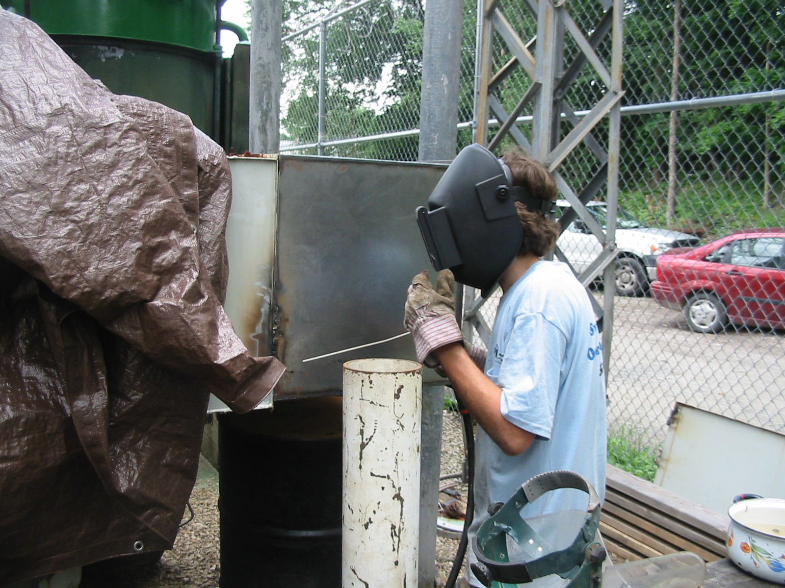
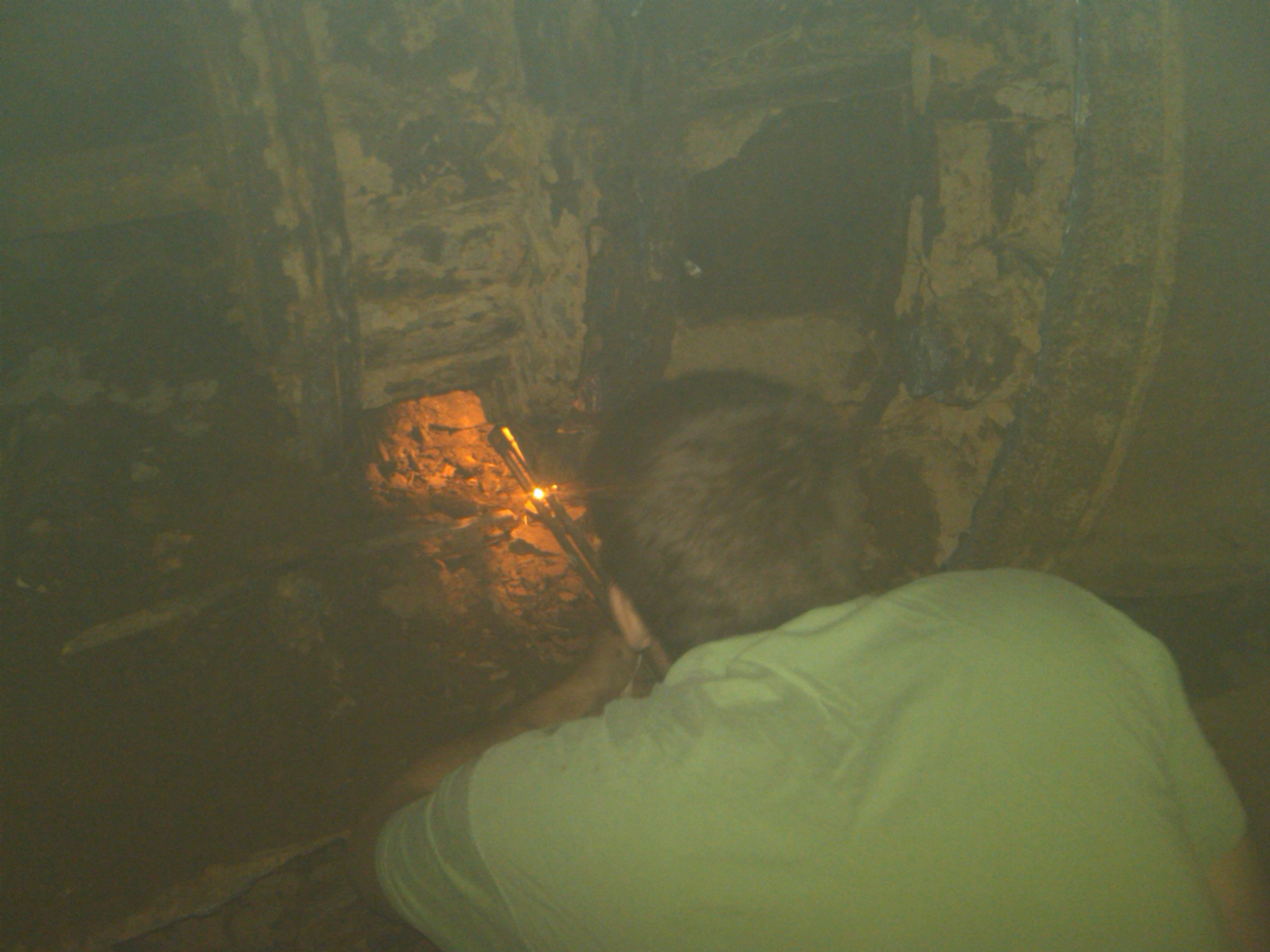
Davis starts his surgical incision. Note the small pressure case to the right. The Clark's (of Clark's Trading Post Fame) 15 years previously removed a smaller turbine by drilling a million holes in the little cover. They than smashed the cover with large sledge hammers. The result was the same but Davis and I preferred the thermite bars.
+ Davis Hobbs dancing with the devil!! The heat was so intense that with an ambient temperature of over 100 degF we could only do two bars each. When we stopped we started shivering uncontrollably because the 100 degF day was so cold!!! See the Livermore Falls sidebar.
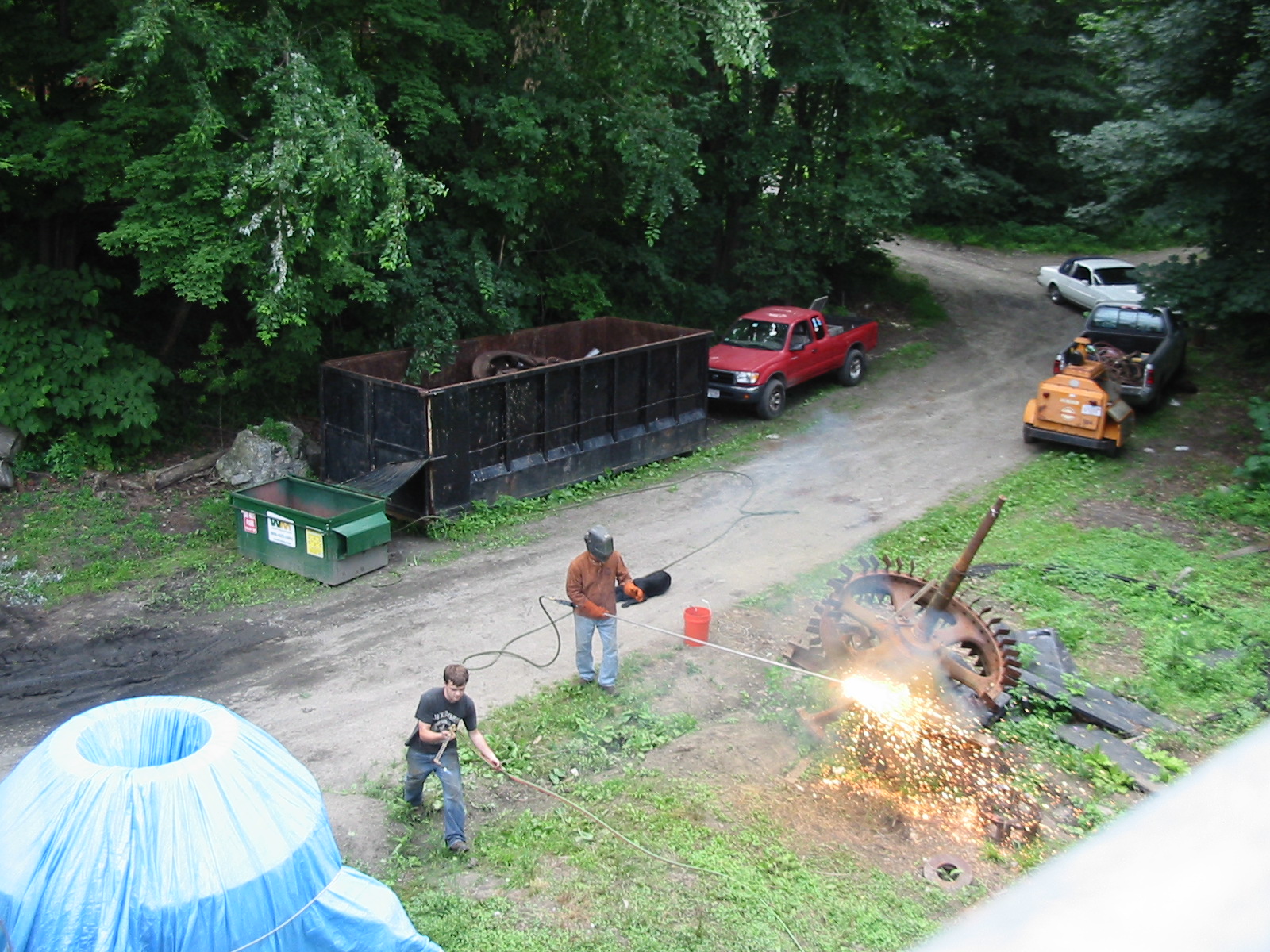
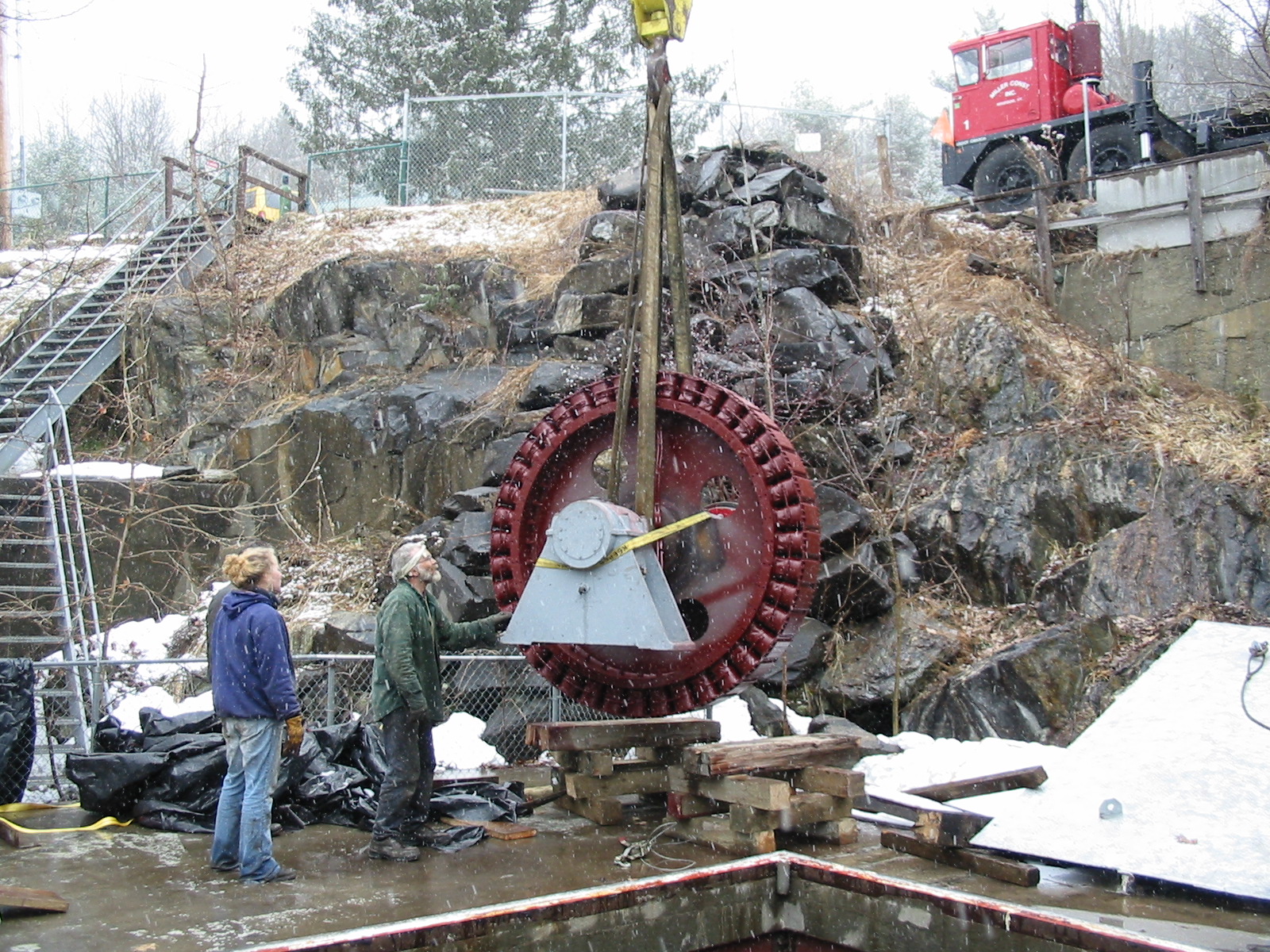
Celesty is slowly pulling the double runners up the hill. Left to right are Davis Hobbs, Ken Smith (aka: Mr. ESAC), me, crazy Chris Krueger and the best employee in the world, Mike Desrouche. We white blasted the runner, magnefluxed it for cracks, turned the bearing journals and coated the runners with Belzona's Super Glide. When it was finished, I did not want to go through this scene again. I rented a truck from Home Depot, loaded the runner on the back with the orange crane, drove down the Mass Pike to the site, and slowly (with some trepidation!!) backed down the hillside. I off loaded the runners with the chainfall located inside the powerhouse door.
Kenny is an excellent rigger. He was a merchant marine engineer and graduated from the Massachusetts Maritime Academy. Whenever I thought we were doing a difficult pick, I remembered Kenny telling me about picking a 10,000 pound cylinder head, off a large marine engine, during a storm!!! Instead of worrying about just gravity, he needed to secure the x-y plane against pitching and yawing of the ship, with no external reference, of where the waves were going to hit. Here, he is removing the dollies from the runners so we can lift it onto the crane.
One set of freshly rehabbed runners, about to go down the Mass Pike, to be backed down to the Woronoco Powerhouse. I was really hoping the brakes would hold and they did!!!We do nice work!!!
Out with the bad!!! One very corroded and damaged Leffel, 54 inch, "J" runner. Mike Desrouche, Ronnie Johnson and Marshall Smith riggers. Back in with the good!! $ 130,000 later, one new, replacement American Hydro runner!! Marshall Smith, Dave Hobbs, Mr. ESAC and Mike Desrouche off loading the new runner. March 8th, 2009, added Christiana, Jolly, Trump and 1902 Lombard Catalouges. March 5th 2009, added link a link to "Treatise Relative to the Testing of Water-Wheels and Machinery, with Various Other Matters Pertaining to Hydraulics" James Emerson, Holyoke Testing Flume, 1878. March 3rd 2009, added three Lombard Catalouges, four articles on cavitation and links to the classic textbooks, Waterpower Engineering by Dan Mead and Hydraulic Turbines by Daugherty.
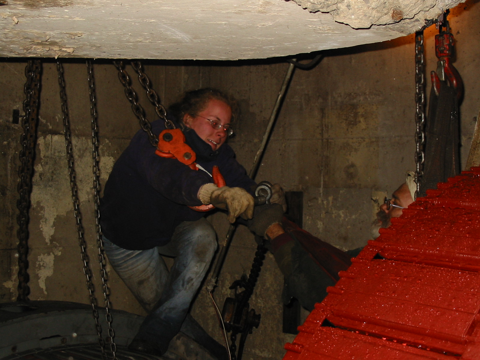
Celesty and I are lowering the Leffel, 39 Inch, B-2 runner into the No. 2 pressure flume. The new main shaft was created by "The Wizard", on our 28 foot long, Poreba, roll, lathe. Celesty and Mike had just used the 3000 ft-lb, hydraulic torque wrench to tighten the 1/2 coupling onto the top of the runner. We are standing on top of the Westinghouse generator flange that I carved from the carcass of the number two generator with the thermite bars.
Can you imagine inventing a turbine, drawing it up, making the patterns, casting the iron parts, machining the pieces, assembling the machine and shipping it off to the famous Holyoke Turbine Testing Flume for efficiency tests. Now, imagine paying the famous Mr. James Emerson, for those tests and having this letter, not only sent back to you, but also published in an engineering textbook!! Mr. Emerson really needed a modern course in client relations! This was in the famous, first, edition, that was banned by the Roman Catholic Church, the only engineering textbook ever banned!!! This was not in the later editions of the book, "Treatise Relative To The Testing of Water-Wheels and Machinery, Also of Inventions, Studies and Experiments with Suggestions from a Life's Experience", James Emerson, Williamsett, MA. 1894. It was the latter part of the title and of the book that got Mr. Emerson in trouble with the Church.
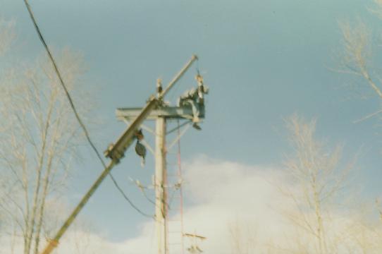
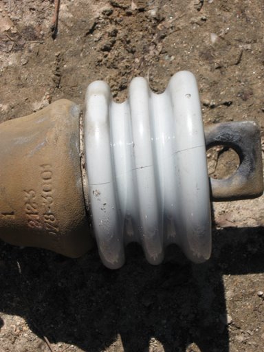
Collins blew a 13,800 volt fuse yesterday. The crew opened the air break switch and killed the line. After inspecting the blown line, we found this burnt bushing. Notice the hairline crack in the porcelain. Water got in the crack and the high voltage tracked down the water to ground. Note the burned metal in the eye. No one saw it happen, but it must have been a spectacular explosion.
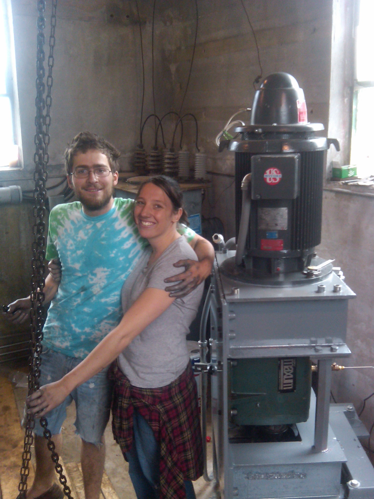
Celesty has just helped finish replacing the Ropac mechanical seal at the Collins site. The seal was in the No.2 ESAC unit. What other turbine mechanic cannot work without her ear rings!
Will and Celeste reassembling the GE thrust bearing at Turners Falls. They have installed the bearing and thermocouples and are just sliding on the cooling fan. The next morning we all left for three weeks in the Yucatan Peninsula.
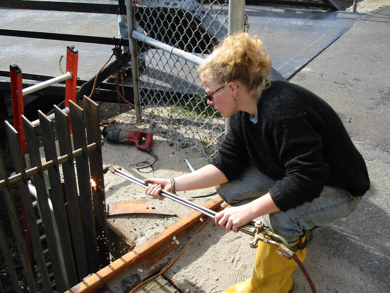
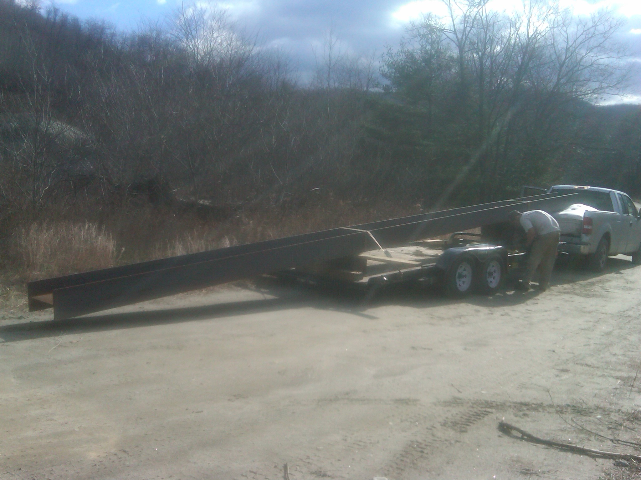
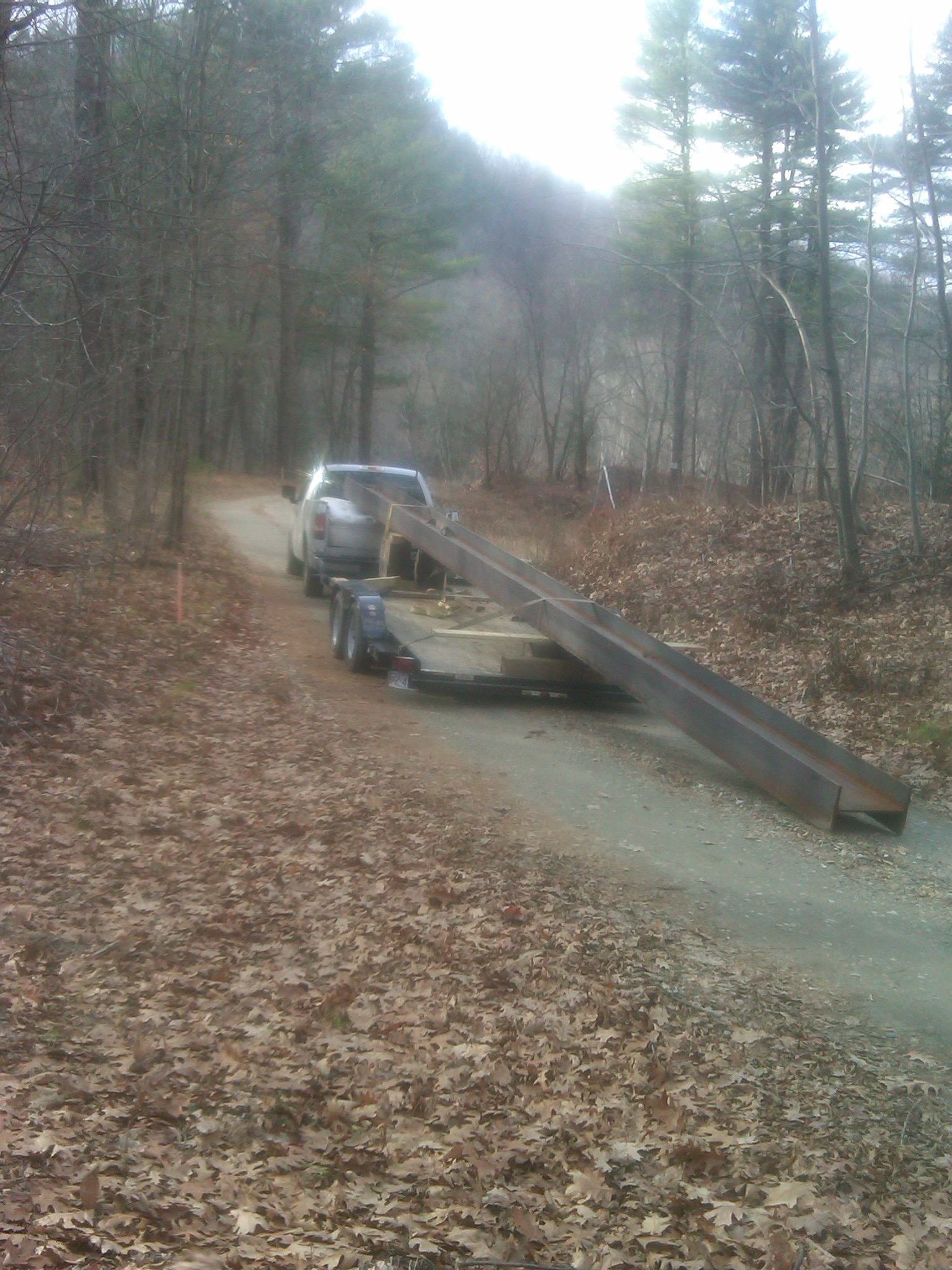
Will cutting the 30 inch main support beam for the new stoplog structure at Woronoco Hydro. Here he is 11 years old and this is an enormous I-beam! Celesty rigging out the back roller shaft at Consolidated Edison's, Gardiners Falls Station. We were onsite to repair the canal waste gate's operating mechanism. The shaft was so long and heavy that we had to use two three ton chain falls hung from beam clamps attached to the overhead roof beam. Celesty adjusting new trash racks at Consolidated Edison's Dwight Station. The rack section was being held out by a 600 volt conduit. Rather then moving the conduit, Celeste picked up the torch and adjusted the racks. That is a 30" wreckers torch she is using. It has been used on many jobs!!
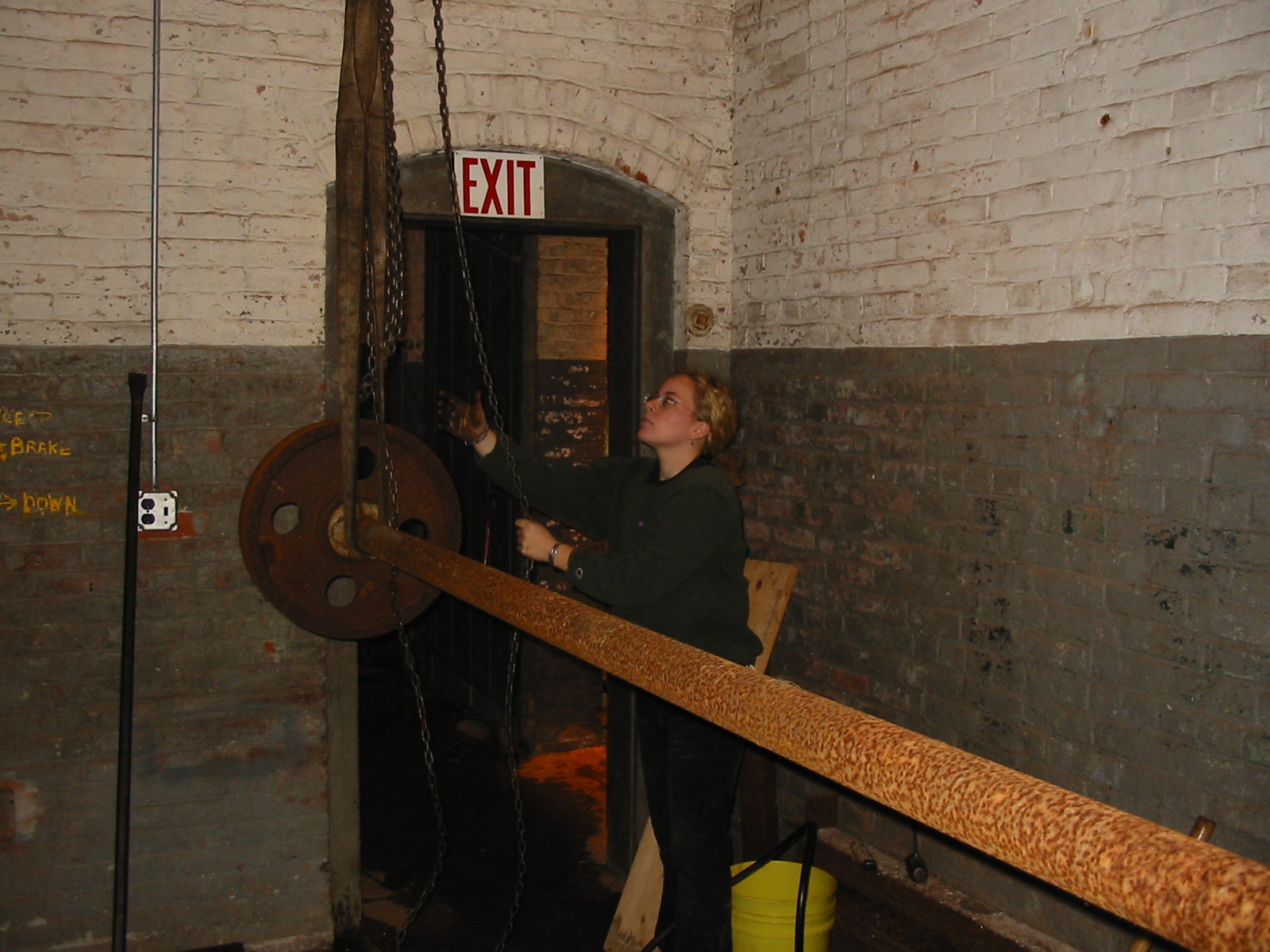
Celeste rigging in the main waterwheel support bearing at the Slater Museum in Pawtucket, R.I.
Lovell Comstock using his Mack truck with a Peppin backhoe to load the four 33 inch, Hi Test runners onto the trailer.
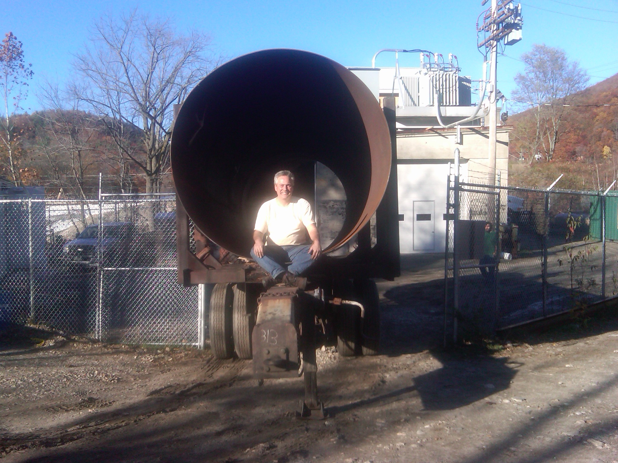
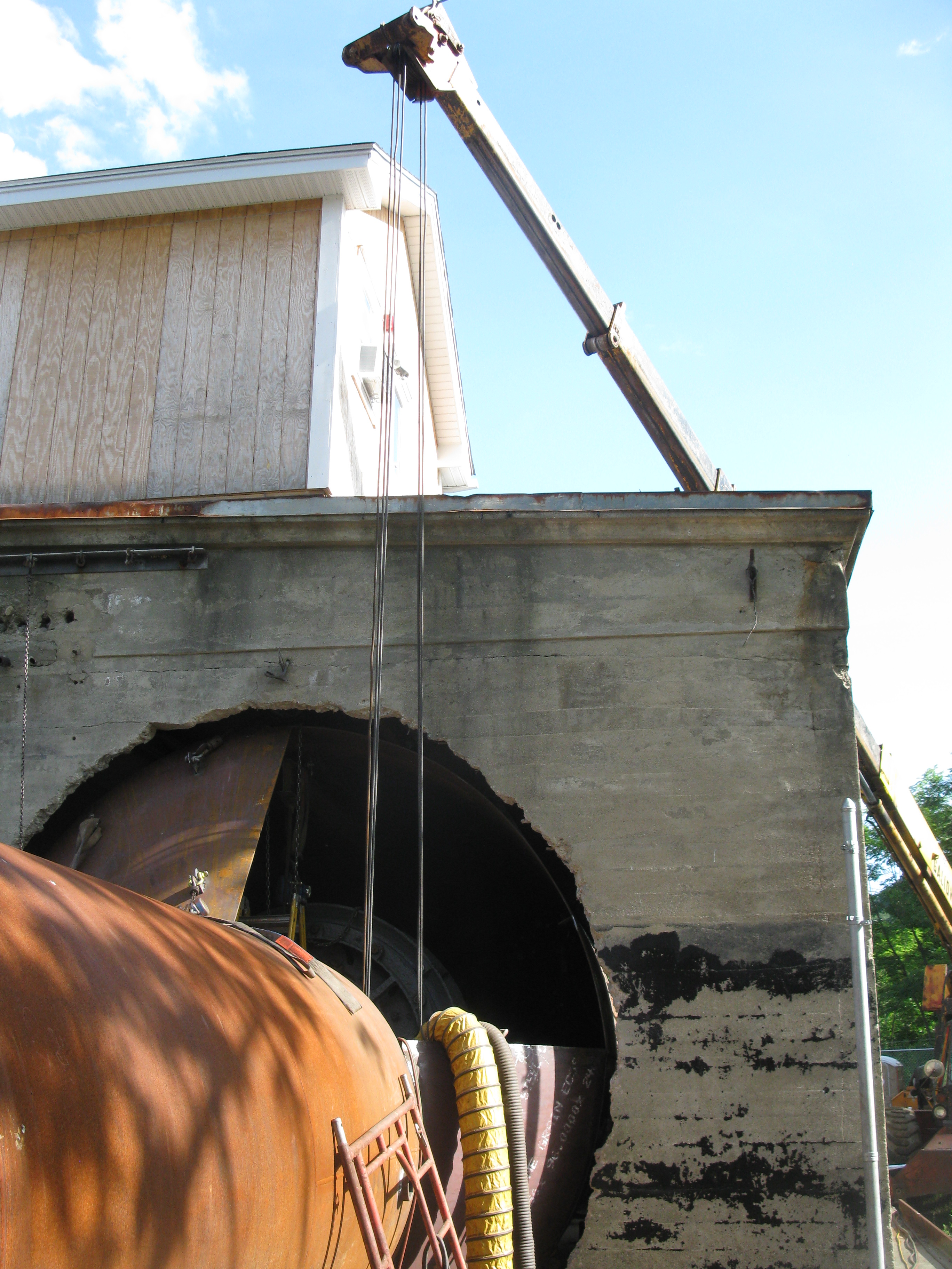
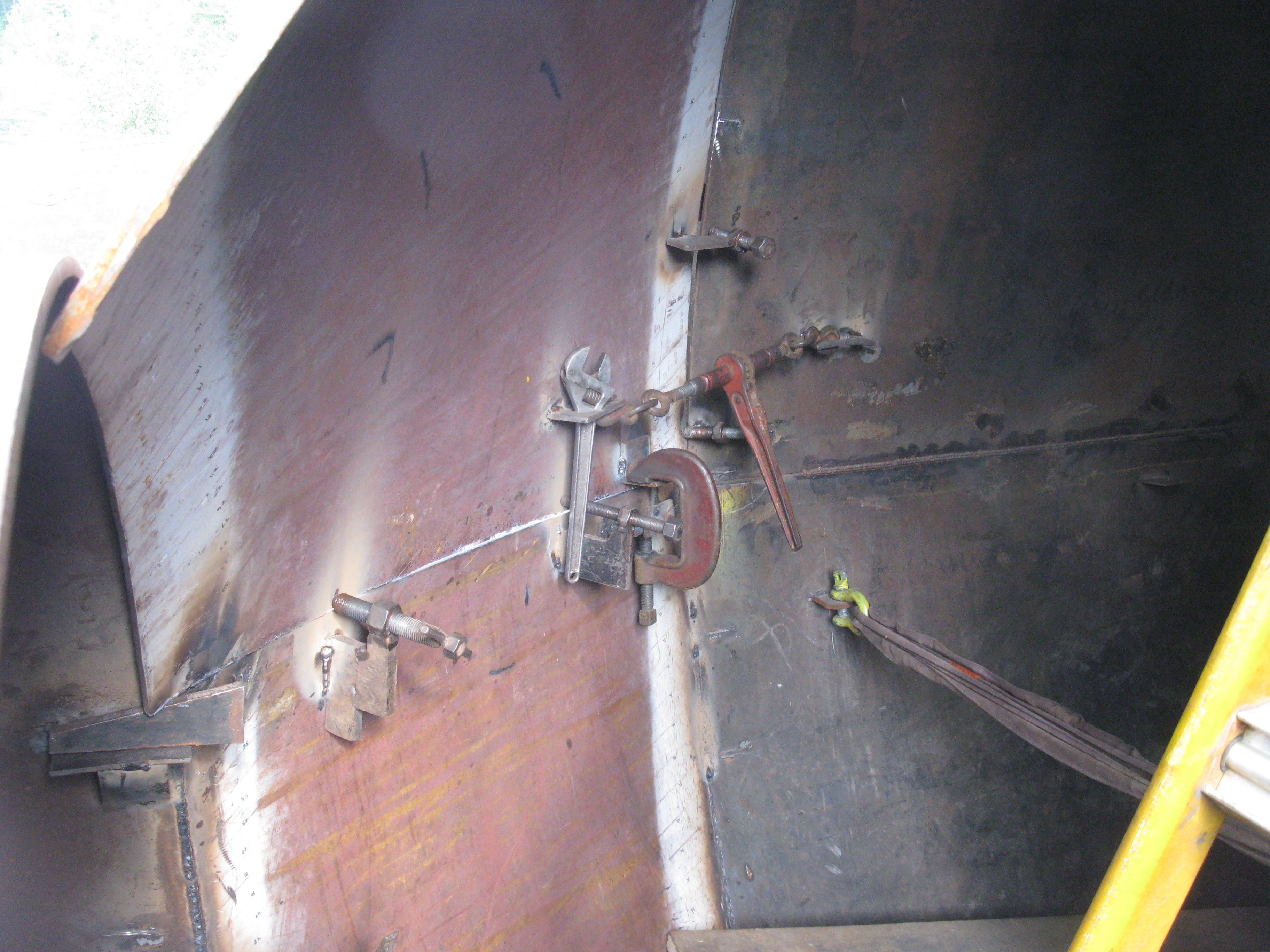
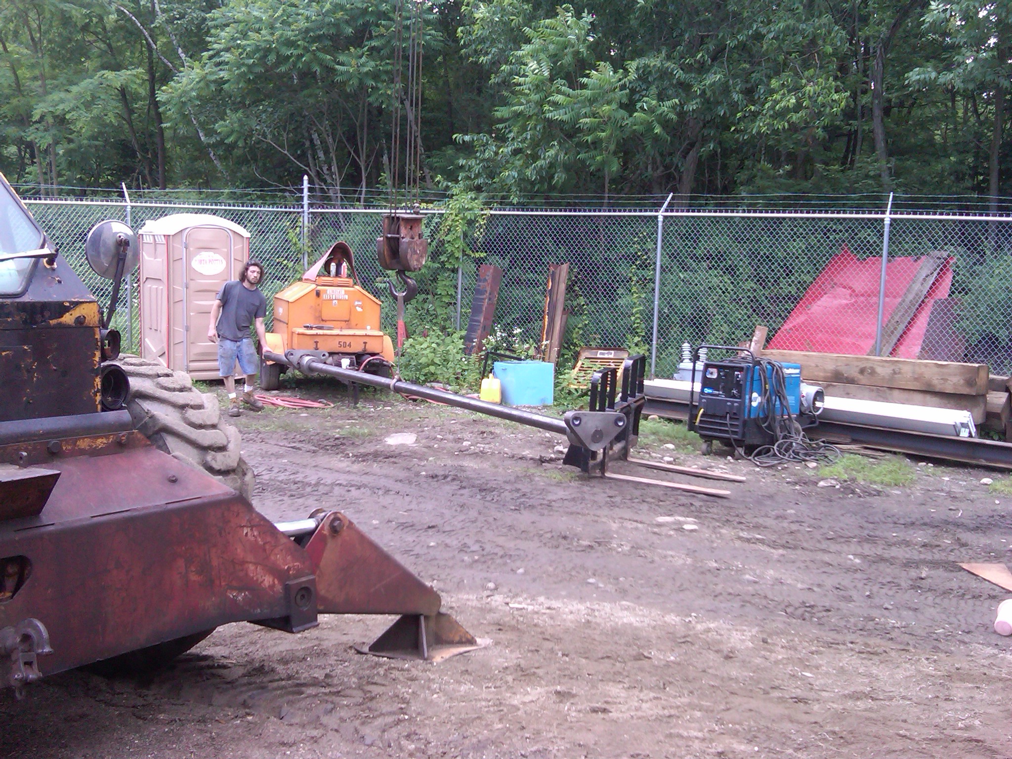
Will determining the best place to set up the crane and how to slice the penstock and draft tubes.
Kenny Smith and Celesty adjusting the new racks at Dwight HEP.
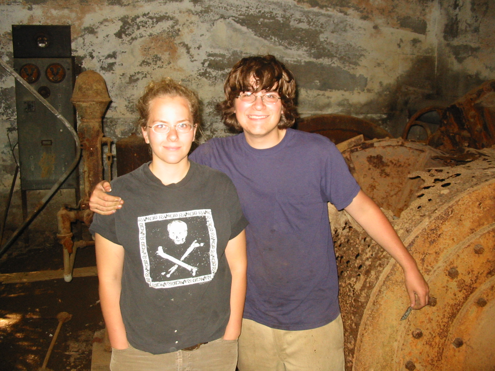
Will and Celeste in the ruins of Appleton. Dave and Seth Wright would be dismayed at this destruction.
Celesty taking down the nameplate data at Bristol.
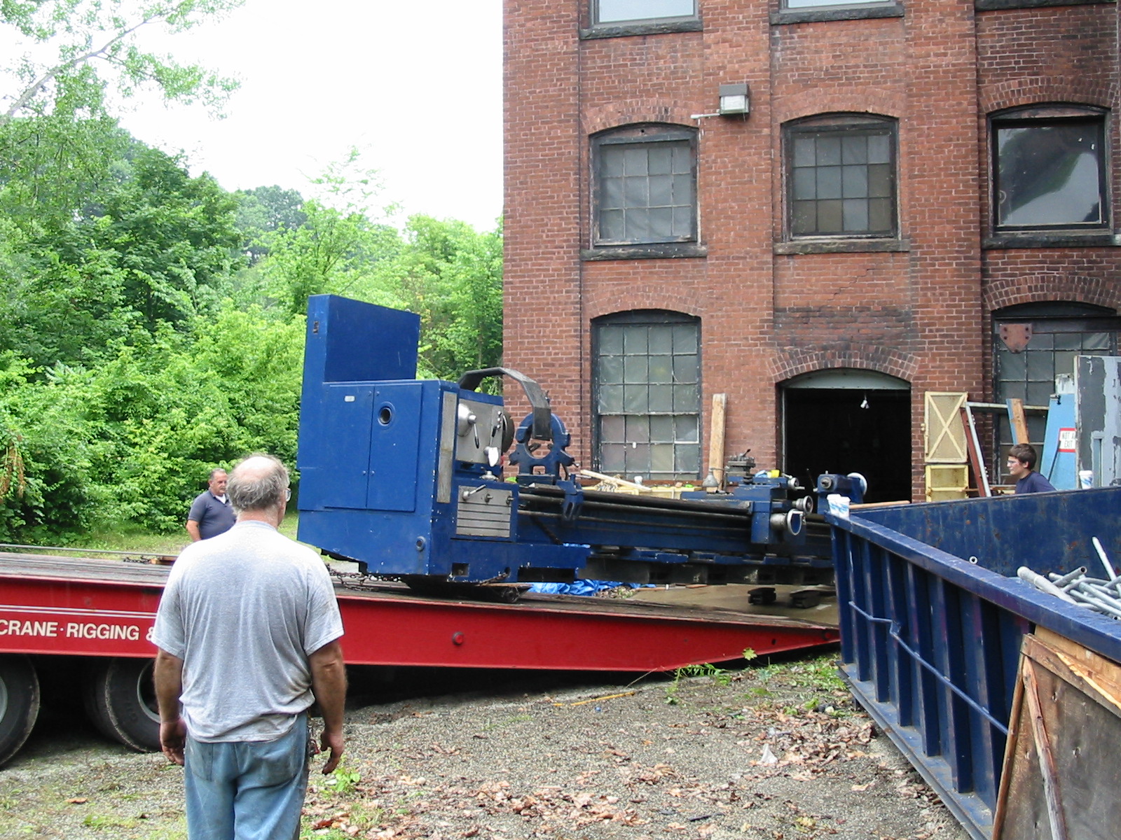
Celeste operating the Landoll rig as she carefully pulls the Poreba lathe onto the truck.
Celeste pulling the 35 foot long, 40,000 pound, Poreba roll lathe onto the truck to bring back to the machine shop. Warren Fay (The Wizard), Donny and Will Fay watch.
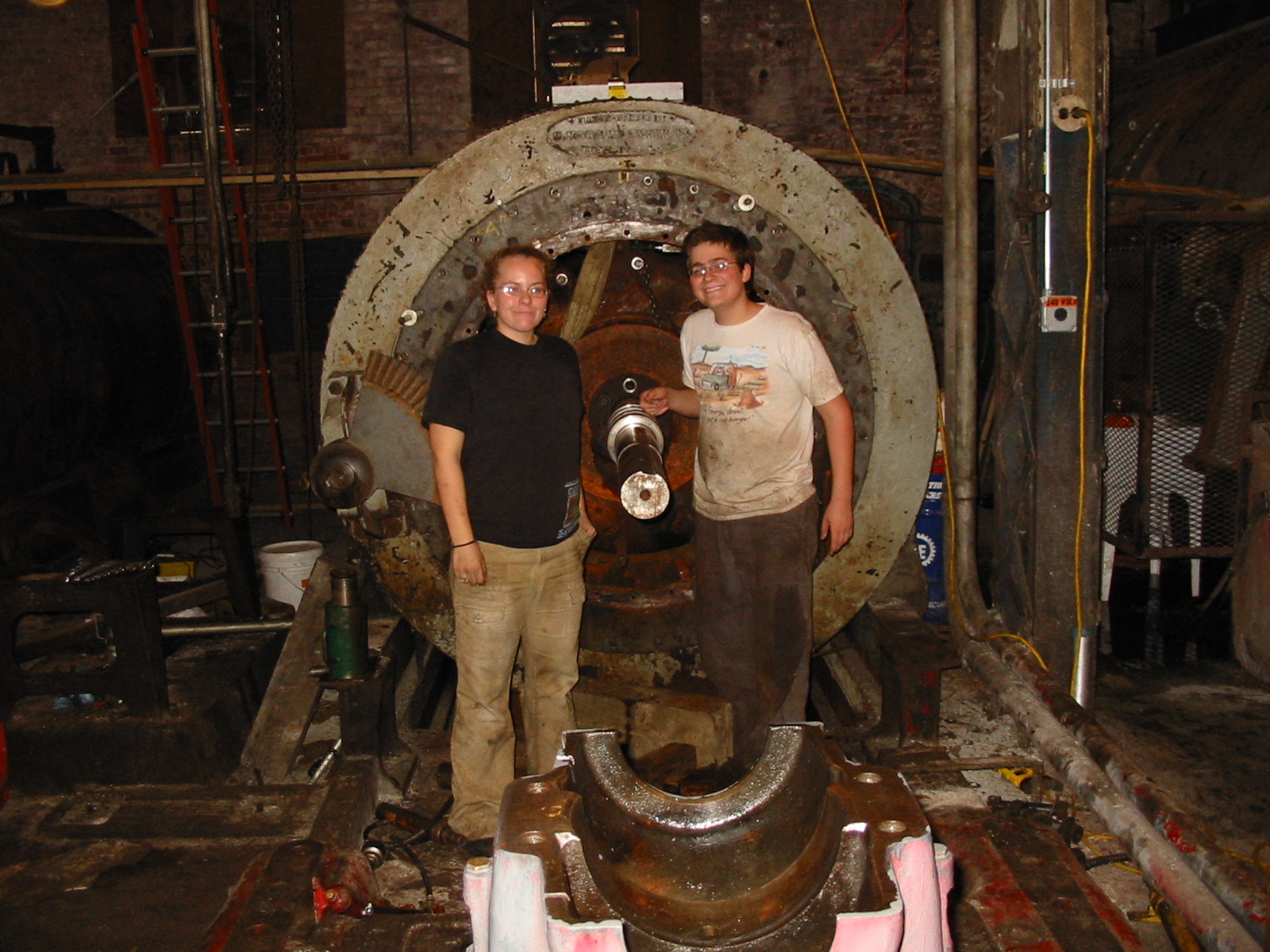
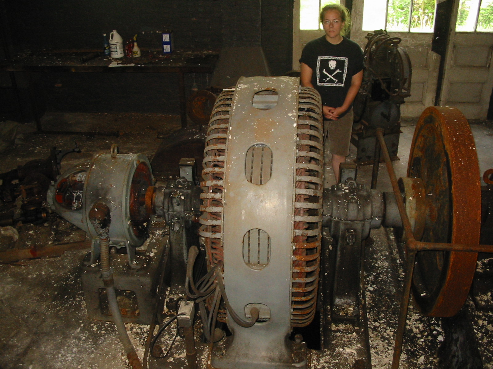
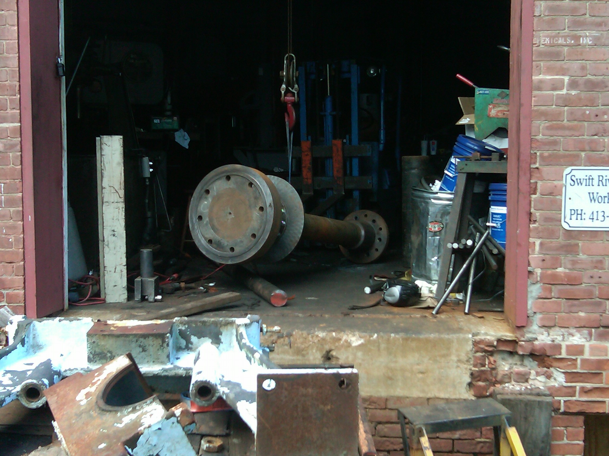
Will and Celeste dismantling the wet end of Woronoco Hydro's No.2. They have removed the front gate case. They are flanking the exposed main shaft and front runner. Will and Celeste wonder whether to pull the equipment or rebuild the site!!
Will jacking up the 60 inch Bullard Turret Lathe
A view of the turbine suspended from the chainfalls. All in a days work! 60 inch Bullard moved to loading dock by Celeste, Will, Ron, Warren & Bill
Celeste and Mike installing the No.2 unit's shift ring.
Will Fay finishing up the quarter block assembly for turbine two. He is fitting the new bronze screws.
FERC ordered us to place an emergency oil spill pan under the transformer at Collins. We needed to get it out to the powerhouse which is set in the river. It was too bulky to drag across the rocks and lift up. I tied a cable to the superstructure, made a loop on the other end and put it on the crane hook. We belted the stainless steel pan to a snatch block. As I lifted up and extended the crane boom, the cable became taunt and the pan was lifted up and it rolled across the chasm to the waiting arms of our riggers. We placed two ten foot, aluminium I-beams on top of the steel superstructure. We hung four five ton chain falls at the corners of the transformer. We lifted the transformer up, slid the pan underneath and set the transformer down into the pan. End of a long day! The gang of four!!! Carol, Celesty, Ian, and Will taking a break from sending the transformer pan across the river.
Will and Celeste prospecting for "houille blanche". Will!!! watch out for high hazard dams!!!
Celesty and Hugh are using the 30 ton porta-power to drive the slip ring collector on to its seat. Celesty installing a rebuilt Rodney Hunt filler gate. This gate is used to fill the turbine pit prior to lifting the 8 ft high by ten foot wide pit gate. The lifter had two Timken tapered bearings that were rusty. We replaced both bearings, sandblasted and painted the lifter. Will welding the containment box for the 800 amp circuit breaker to connect the rebuilt No. 2 unit to the main bus bars. Celeste and Will rigging in the slip ring cover on Pepperell No.2's reconditioned unit. Celeste, Will and the "Wizard"
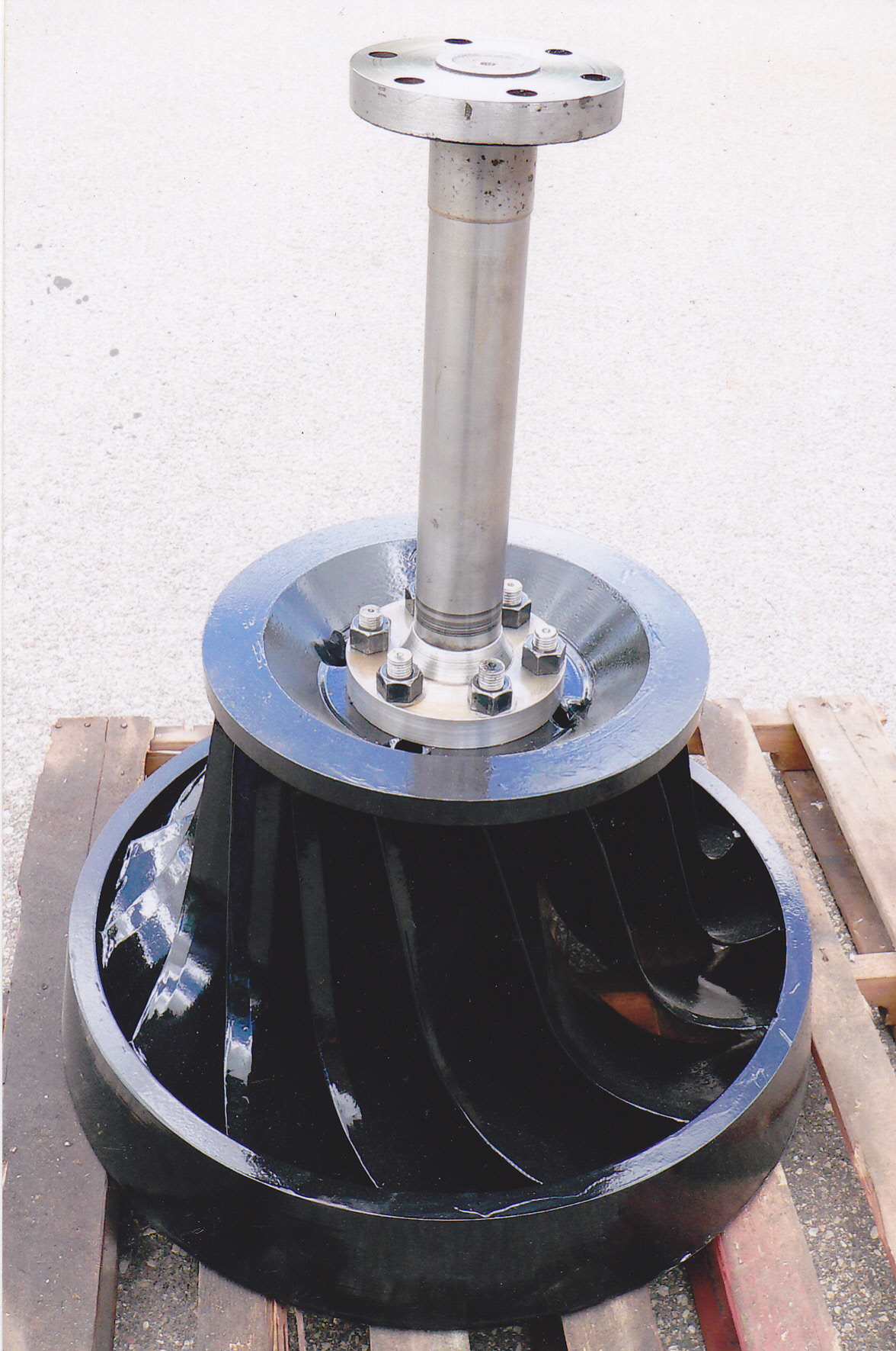
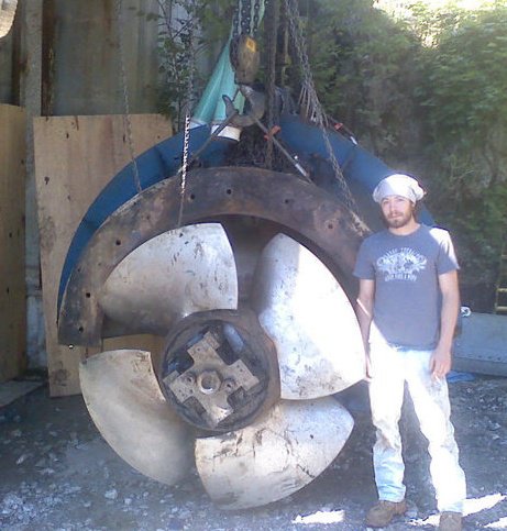
Will white blasting the Golden Pond Hydro Kaplan hub. Note blade trunion bearings covered with plywood covers.
Celesty and Mike Desroche preparing the camel back hump for Woronoco No. 2. Note the freshly, steel lined pressure case. Note the new pins in the rear gatecase.
Celeste removing the old slate switchgear from Thorndike Lower HEP. Celeste has been operating the crane for years. Lance is taking pictures of me taking pictures!
Celeste rigging the Brockway Mills stator into position. This was really quite difficult. The crane dropped the rotor down 60 feet. Then it had to be pulled side ways beneath the powerhouse floor. Celesty has transferred the load from the crane hook to a 10 ton chain fall attached to an eye bolt fixed to the ceiling.
Celeste and Chris Kruger dropping the Brockway Mills rotor through the hatch in the powerhouse roof. The snow progressed into a blizzard. All in a days work!
Celeste and Chris Kruger close quarter rigging the Brockway Mills rotor into position. This rotor weighs in excess of 14,000 pounds. Watch out Celesty!!!!
Celesty Fay constructing her first dam at Mill Road. She is two years old here!!! Note the giant baloney curl looped over her left shoulder.
The Wizard, Kenny Smith and Celesty pulling the 72 inch propellor out of the ESAC unit at Collins. We needed to replace the Ropac mechanical seal that prevents water from leaking into the bulb. The draft tube has been sealed off with the concrete draft gate. We had Mike go down in his scuba gear to seal off the gate before we pumped out the turbine throat. Celesty has put in another long day!!!
The four bladed ESAC runner ready for removal from its throat. Mr. ESAC (Kenny Smith) is the country's leading expert on these units!
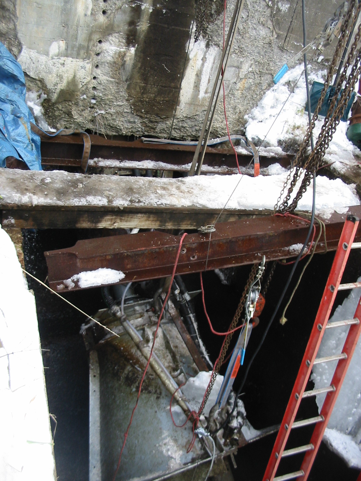
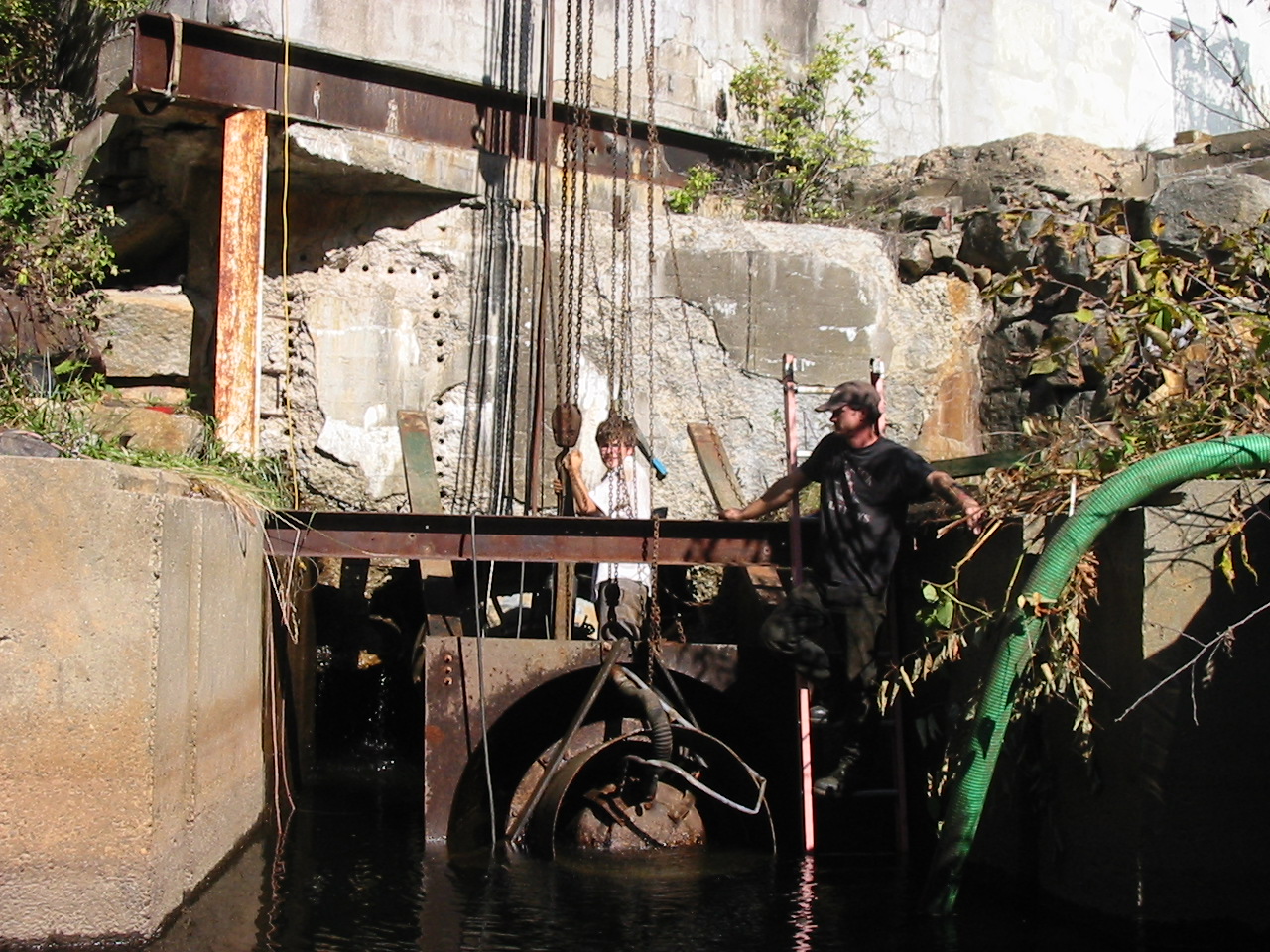
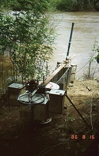
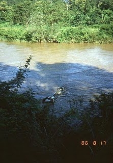
The catastrophic flood, that injured our dam, also shorted out our generator. Here we are pulling the Hydrolec unit out of the tailrace. We previously unbolted it from the penstock flange. Before this we poured over 100 cubic yards of concrete to stabilize the dam. It has been a very busy, traumatic and trying fall season!!
Here Celesty and Mike Desrouche have pulled the 480 volt conduits off of the 480 volt primaries. They are inspecting the wires for short circuits.
We have raised the turbine up out of the tailrace. We built a temporary scaffold for Will to work on. We had to pump the oil out of the unit. We then removed the porthole on the end of the turbine bulb. This allowed us to disconnect the high voltage wires from the generator leads.
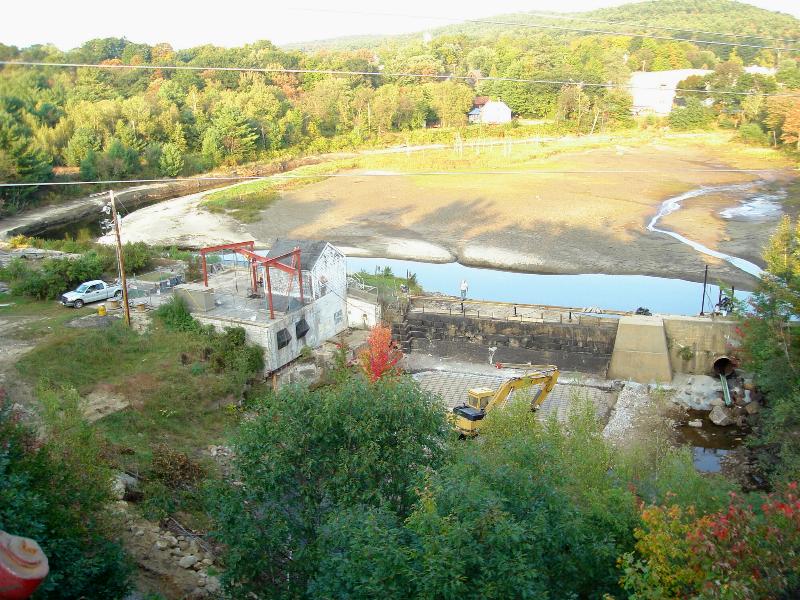
**************FLASH********************* September 27th, 2008 On August 7th, 2008 a microburst hit the intermediate drainage area between Golden Pond Hydro's dam and the main dam at Squam Lake. The flood wave heavily damaged our spillway. It took out the catwalk, flashboards, undermined the spillway apron and shorted out the generator leads. We prepared an emergency, dam, repair permit and applied to the New Hampshire Dam Safety and Wetland's Divisions for their permits. The folks at FERC and the New Hampshire State Agencies responded very quickly. They all worked very hard with us to issue the work permits. We have been working non-stop to repair the dam. We had to first install an access road to access the tailrace and toe of the spillway. Once we had the excavator in place, we cleaned out beneath the apron and formed natural concrete forms out of dry laid stone. We cored three 12 inch diameter cores, 24 inches deep, through the floor of the old apron. We pumped 4.5 cubic yards of concrete beneath the left abutment and then poured another 30 yards beneath the spillway apron. We used vibrators to force the concrete beneath the spillway. Our tailrace training wall had been breached. The wall collapsed into the hole that had been piped beneath it. We formed a new wall on top of the old wall. We pumped another 40 yards beneath the old wall and into the new wall, wooden, forms. We leveled the area in front of the old spillway. We laid 100 pieces of No. 5, 20 foot long, 80 ksi rebar. We drilled the front of the old apron and Hilti glued the rebar into the drilled holes. We poured a new extension of the apron in front of the old one. We have poured 96 cubic yards of concrete as of today.
Bill Fay waves at the tourist train that had stopped on the old railroad bridge. This is before we poured the new spillway apron extension. You can see the No. 5 rebar mat. Please see the attached Picasa album of the destruction and the ongoing repairs. http://picasaweb.google.com/frenchriverland/GoldenPondDamDamage?authkey=nUCJGifjYLw# Notes: Please wait for the pages to load. I used high definition j-pegs for all the pictures and documents. When I loaded them into Front Page, I had to shrink them down with the corner cursor. When I shrunk them, they lost resolution!! It seems counterintuitive to me. Anyways, if you want to print any of the materials, download them into a Word document, blow them back up and then print them. You will have excellent results.
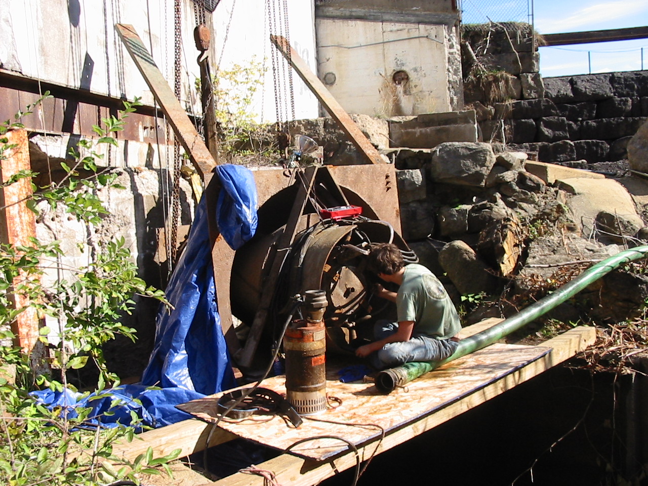
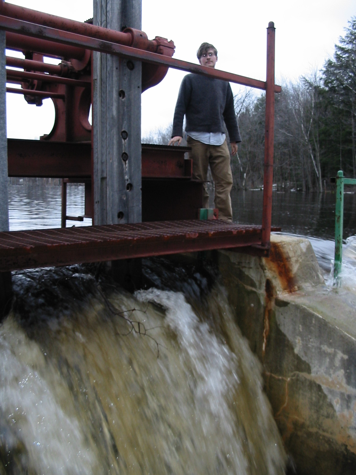
Will standing on top of the newly installed Hydrolec Turbine. The unit was installed two weeks ago and the paint is already coated with algae! Note how the turbine is bolted to the penstock. Its weight is suspended from the pit walls by four, heavy walled, channel-iron, hanger brackets.
Will is flipping the Hydrolec Unit from, vertical to horizontal, in preparation for lowering it into the abyss. The 18 inch I-beam is cantilevered ten feet off the back wall of the powerhouse. The unit can be rolled, on the trolley, over the tailrace and lowered down to the end of the penstock.
The newly rebuilt, Hydrolec H9H, turbine finally arrives at the Freshwater Hydro Station (aka: Golden Pond Hydro) in Ashland. N.H. Will Fay is attaching the lifting belts and shackles to the crane hook. Lee Nichols of Ashland Electric Light Department is operating the crane. The double drop tractor trailer could not drive down the access road so the unit was moved to this smaller truck. The I-beams and pipe supports for the new installation gantry crane came with the same load.
Will and Celeste rigging the 2000 pound, 18 inch I-beam, for the new gantry, at Freshwater Hydro. Previously, when the unit needed work, George had to hire a 90 ton crane to remove it. After it was repaired, he had the crane back to re-install the unit. Celeste and Will designed the gantry and are now fabricating/installing it.
Will has transferred the load from the three ton chain fall to a 5 ton chain cum-a-long. He removed the chain fall and is lifting the beam closer to the support frame. He has installed a lifting strap around the two beams as a safety. The old railroad bridge is in the background.
Celesty is inspecting the No. 2 Unit, at the Lee Pelton Site, in November of 2004. She and Will removed the equipment. They bought the contents of the powerhouse for $ 1000. It was offered to them at the last moment in leau of giving it to the scrappers. It was amazing seeing the two of them, running 30 pound rivet busters, to pry these units out of solid concrete! We still have the three units. Ironically the third unit never ran!. The head losses in the 7000 foot long, 42 inch diameter penstock, with all three units running produced less power than with two units running!!!
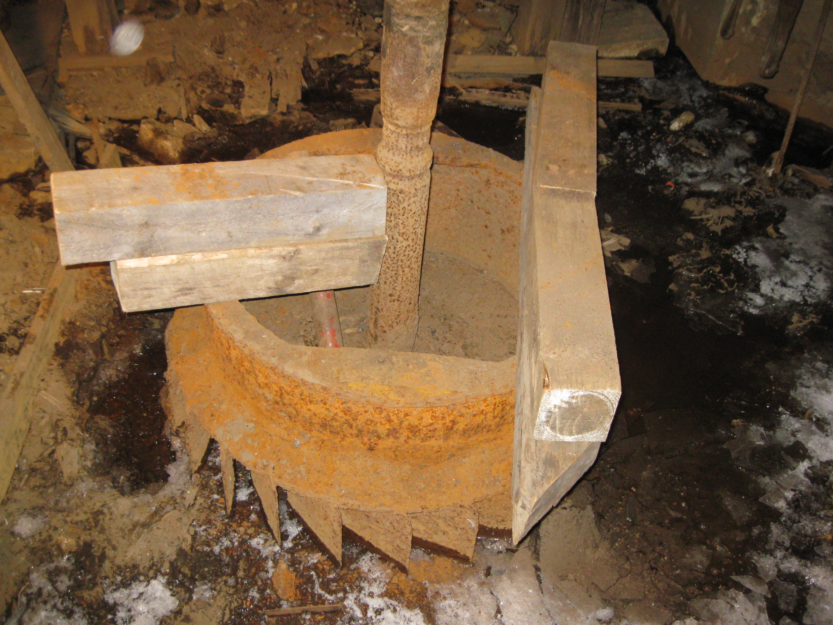
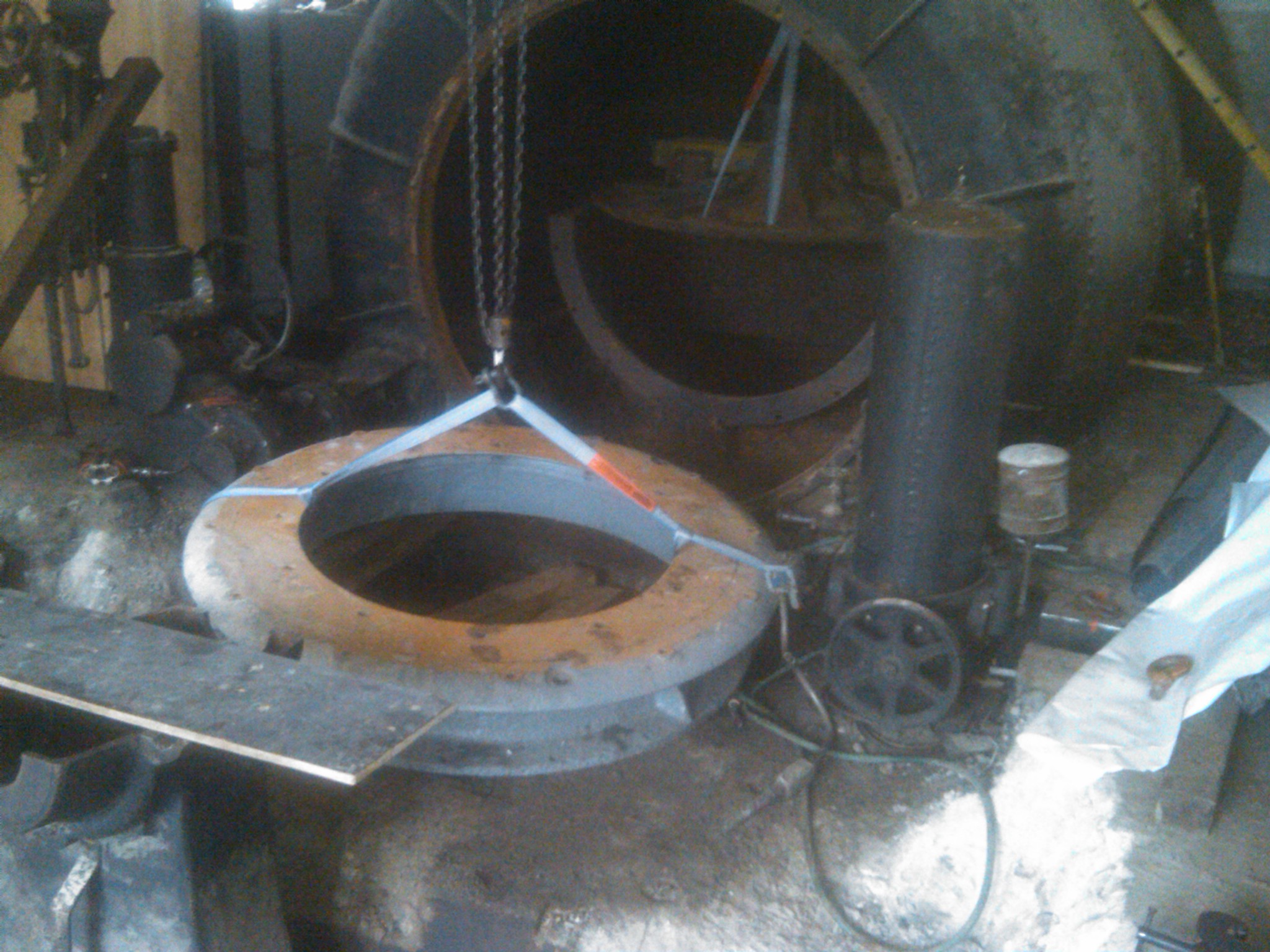
Slater Museum Hercules Turbine. We have removed the cylinder gate cover. You are looking at the cylinder gate. The flat sectors are where the racks bolted on to the top of the gate. The cylinder is partially withdrawn from the guide vane section. We got four weed eaters powered by barbecue tanks. We heated the cylinder red hot. It expanded the cylinder inside the guide section and crushed the rust that was forming an adhesive band between the cylinder gate and the guide vane section. We were able to slip a very long Sawzall Blade down between the cylinder gate and the guide vane section. We worked the blade around the cylinder circumference and freed it up.
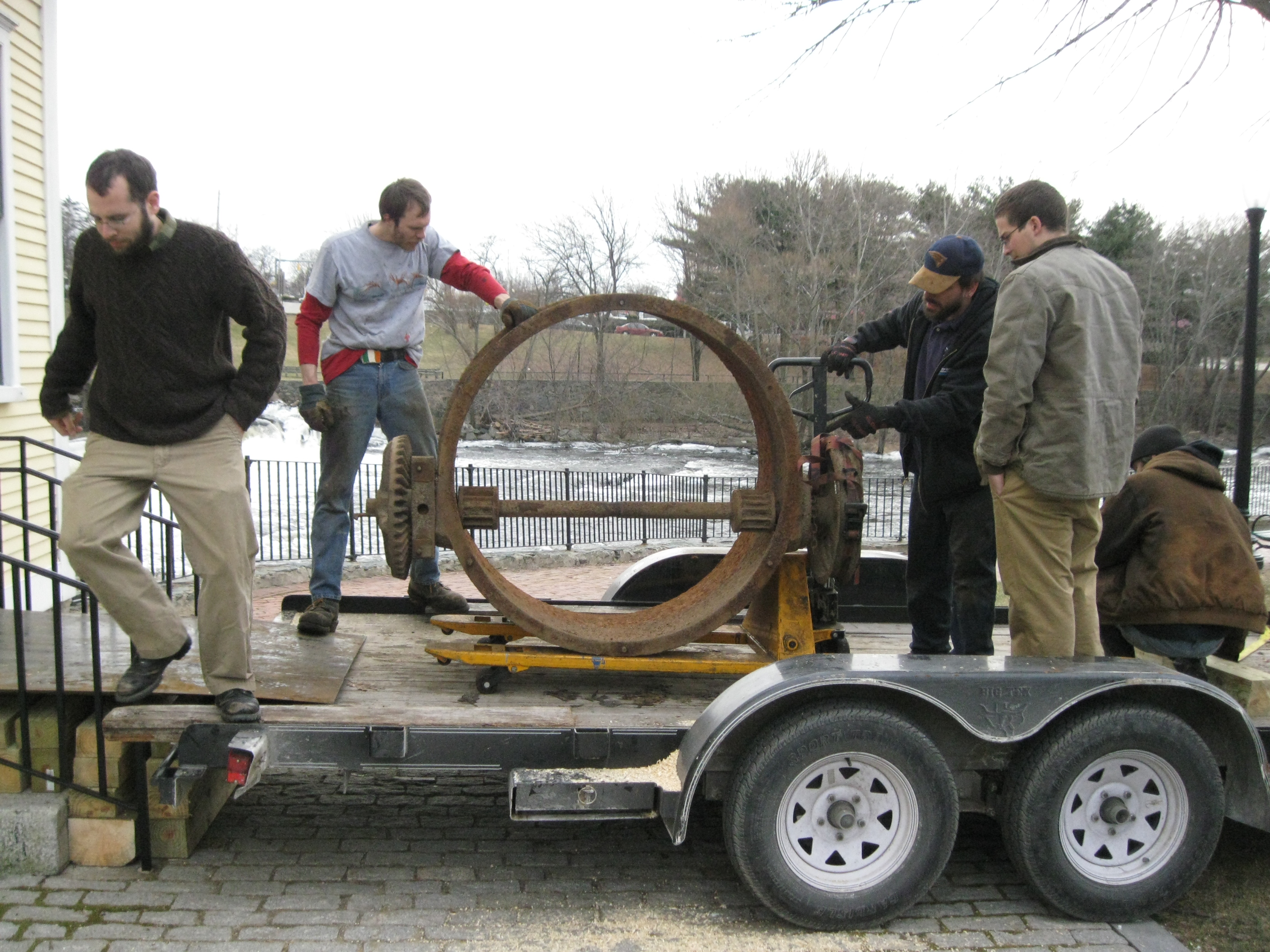
Here we have loaded the cylinder gate cover onto the utility trailer. From left to right, Adrian Paquette, John Remington, Eric Anderson, Will Fay and Mike Desrouche.
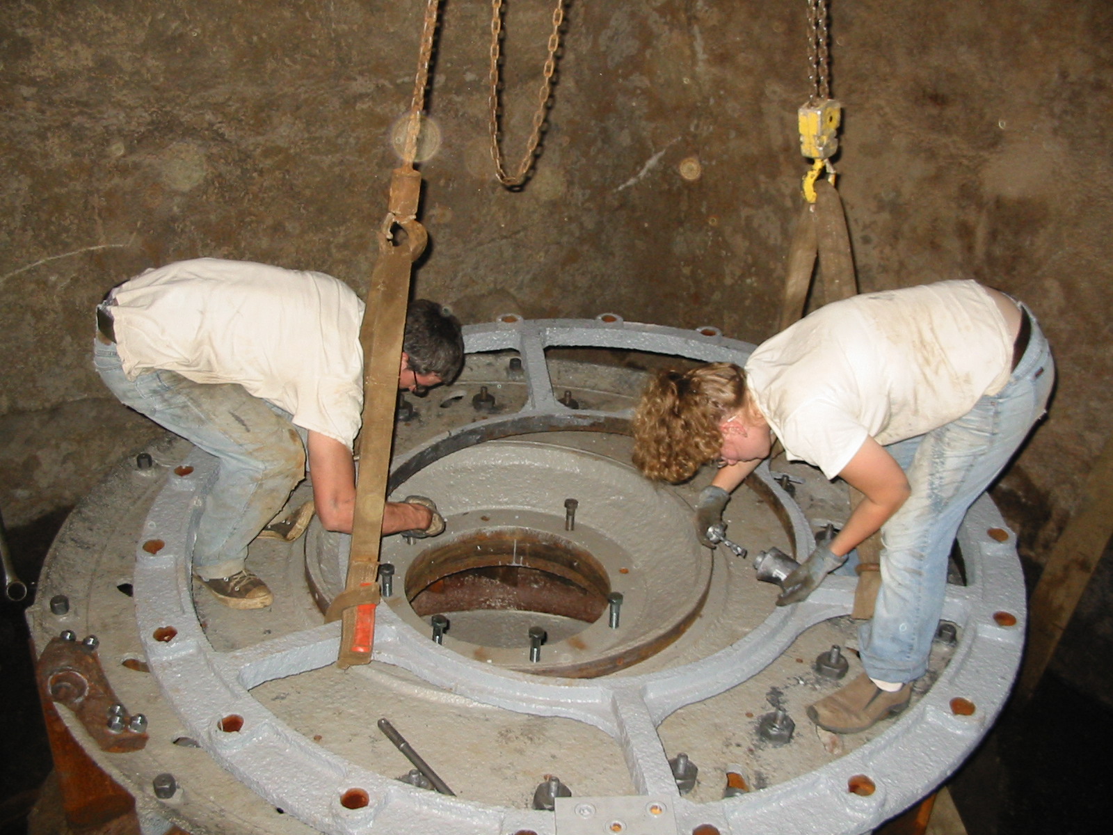
We are rebuilding the Holyoke Hercules Turbine at the Slater Mill in Pawtucket, R.I. It will become part of the waterpower exhibit. We are also restoring a very early Jonval Turbine. Here we are removing the rack covers and gate operators. We have since jacked off the bull gear, removed the cylinder cover, removed the cylinder gate and pulled out the runner. This is a very early Hercules. The runner blades are bolted onto the central hub. This makes the runner replacement quite easy. We are having a maple pattern of the bucket made. We will cast new buckets, machine them and bolt them in place. A thin steel band is bolted around the periphery of the buckets to create the skirt ring. December 7th, 2009. Due excavators fly?? Click below to find out!!!
December 3rd, 2009 *******FLASH*******
Ken Smith and his sons Ian and Marshall are
wrapping up Alternatives Hydro. They are going to go through startup next week. See the Alternatives sidebar for photos from
yesterday. It took 8 years from conception to a brand new
powerplant!!!
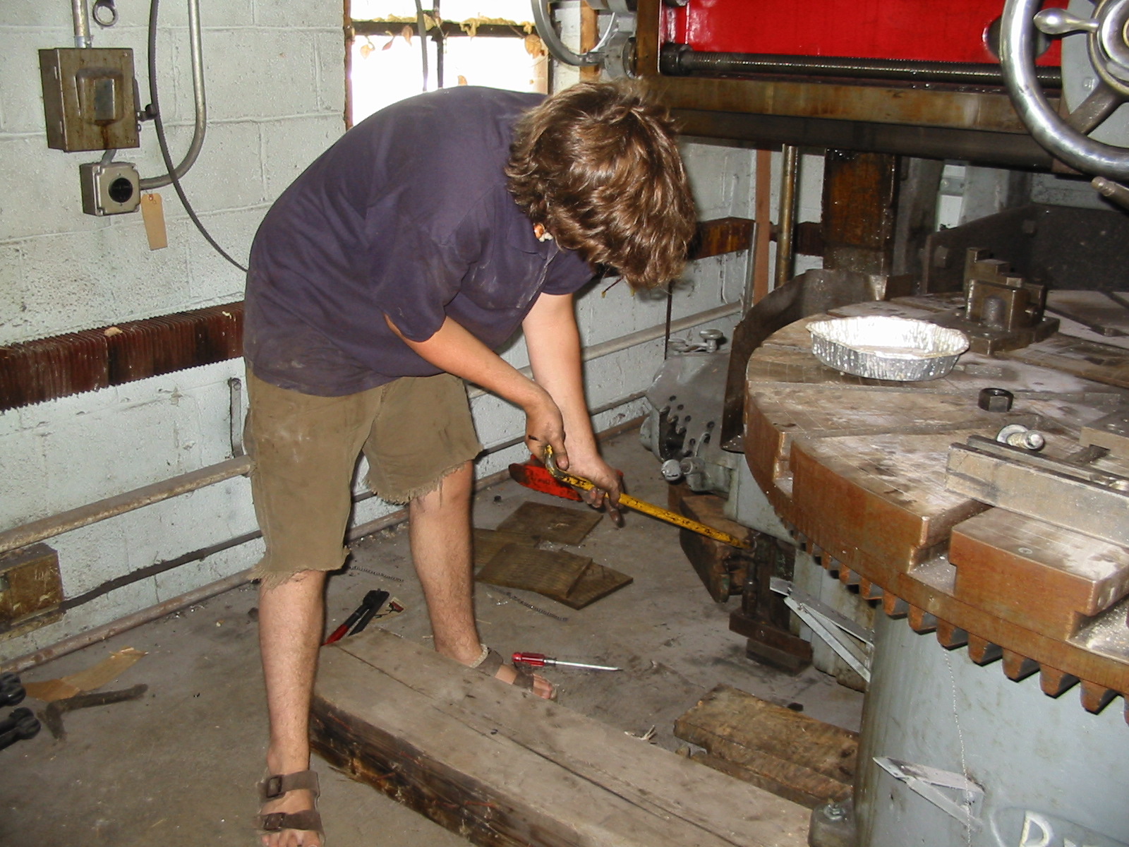
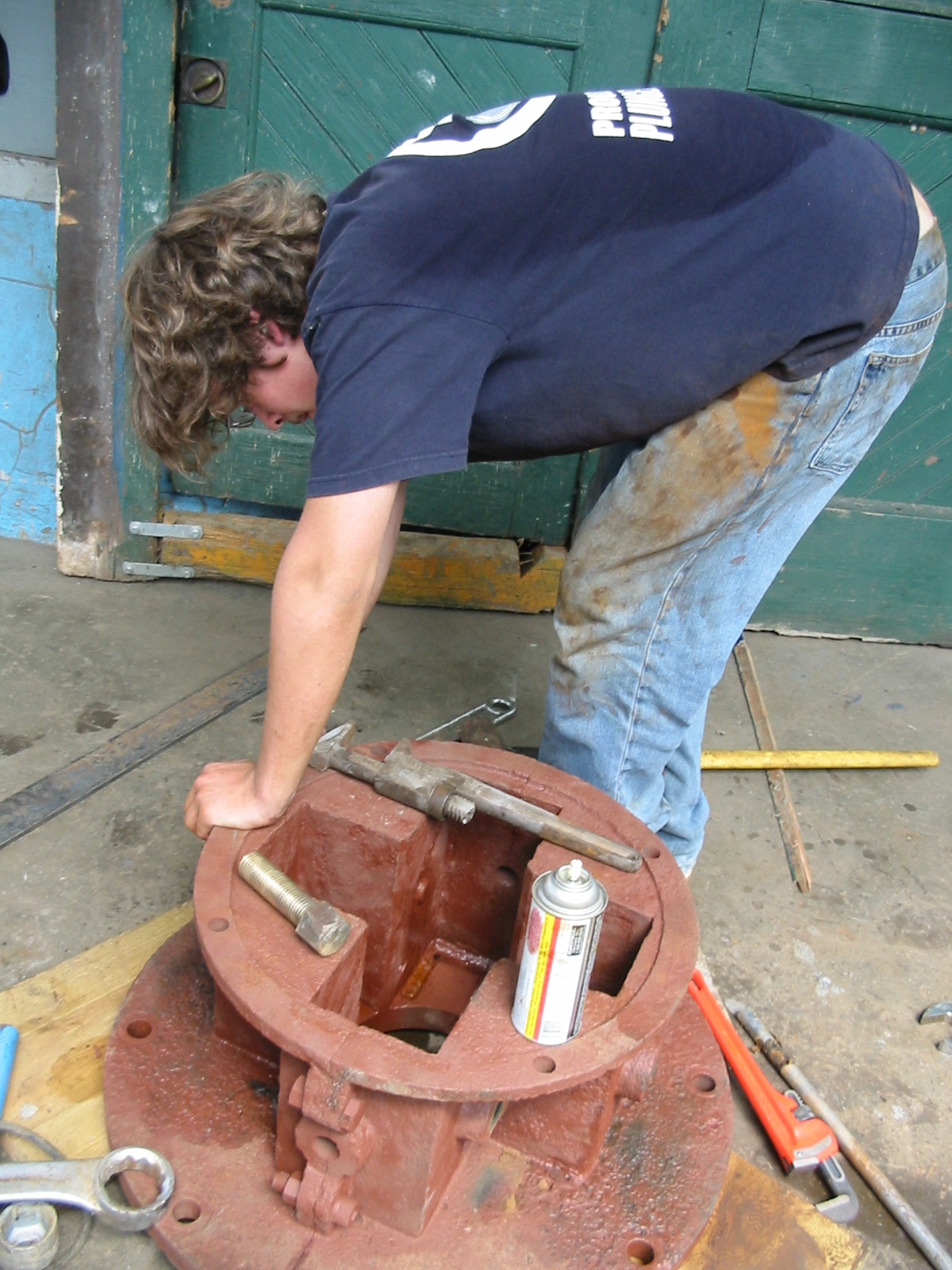
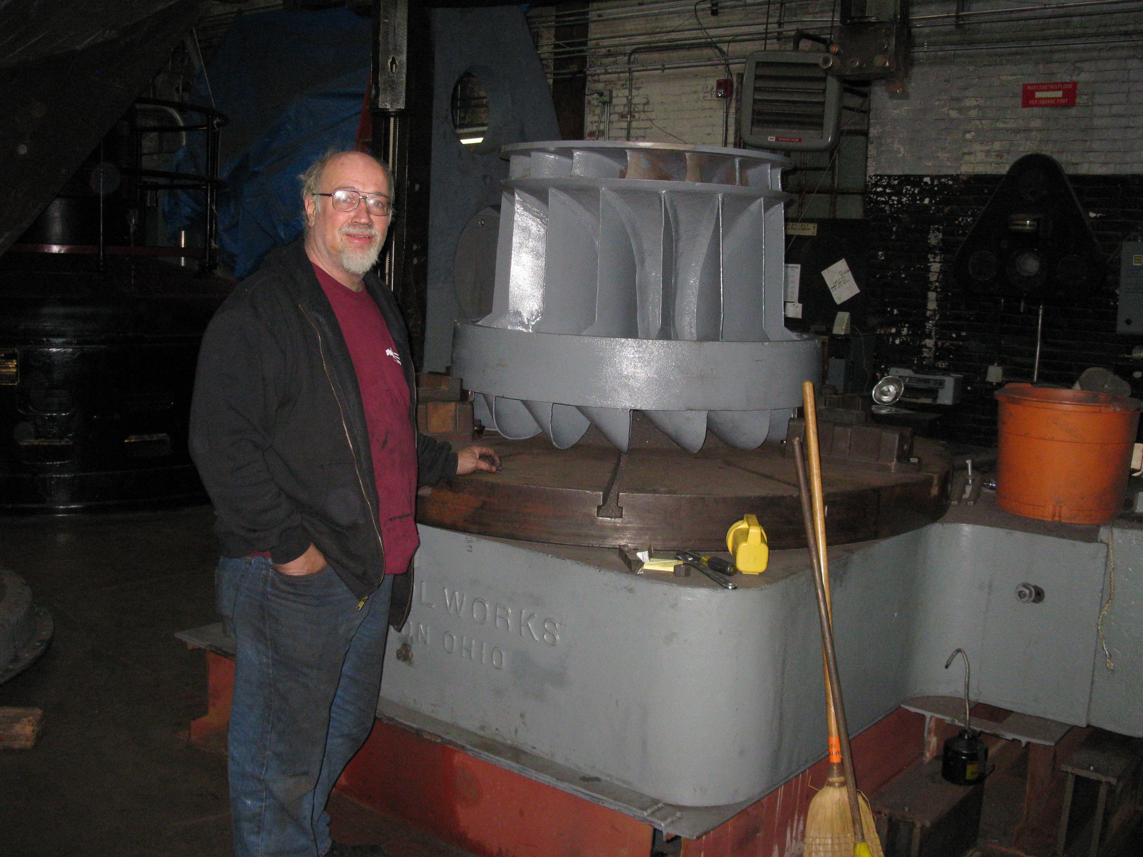
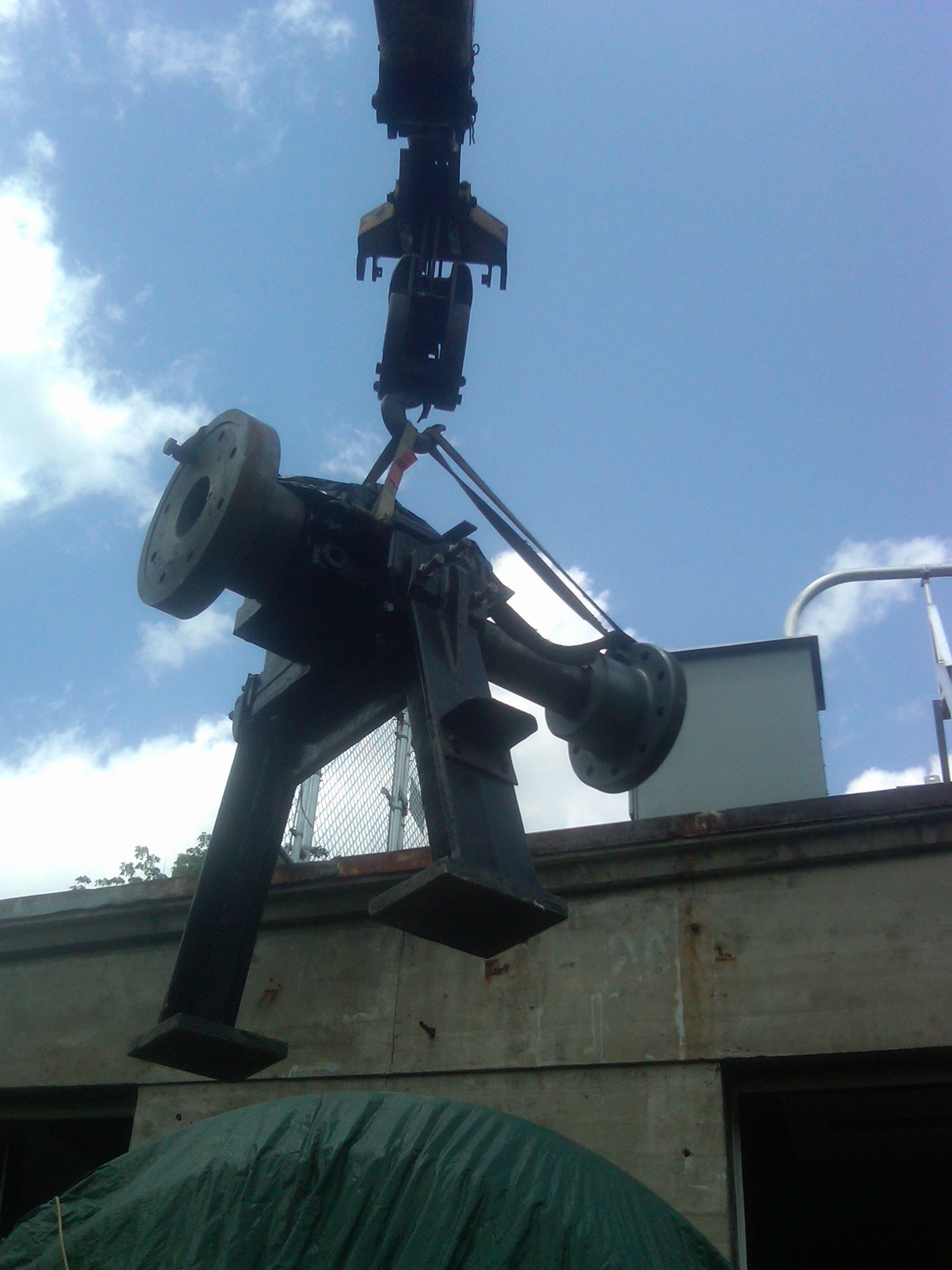
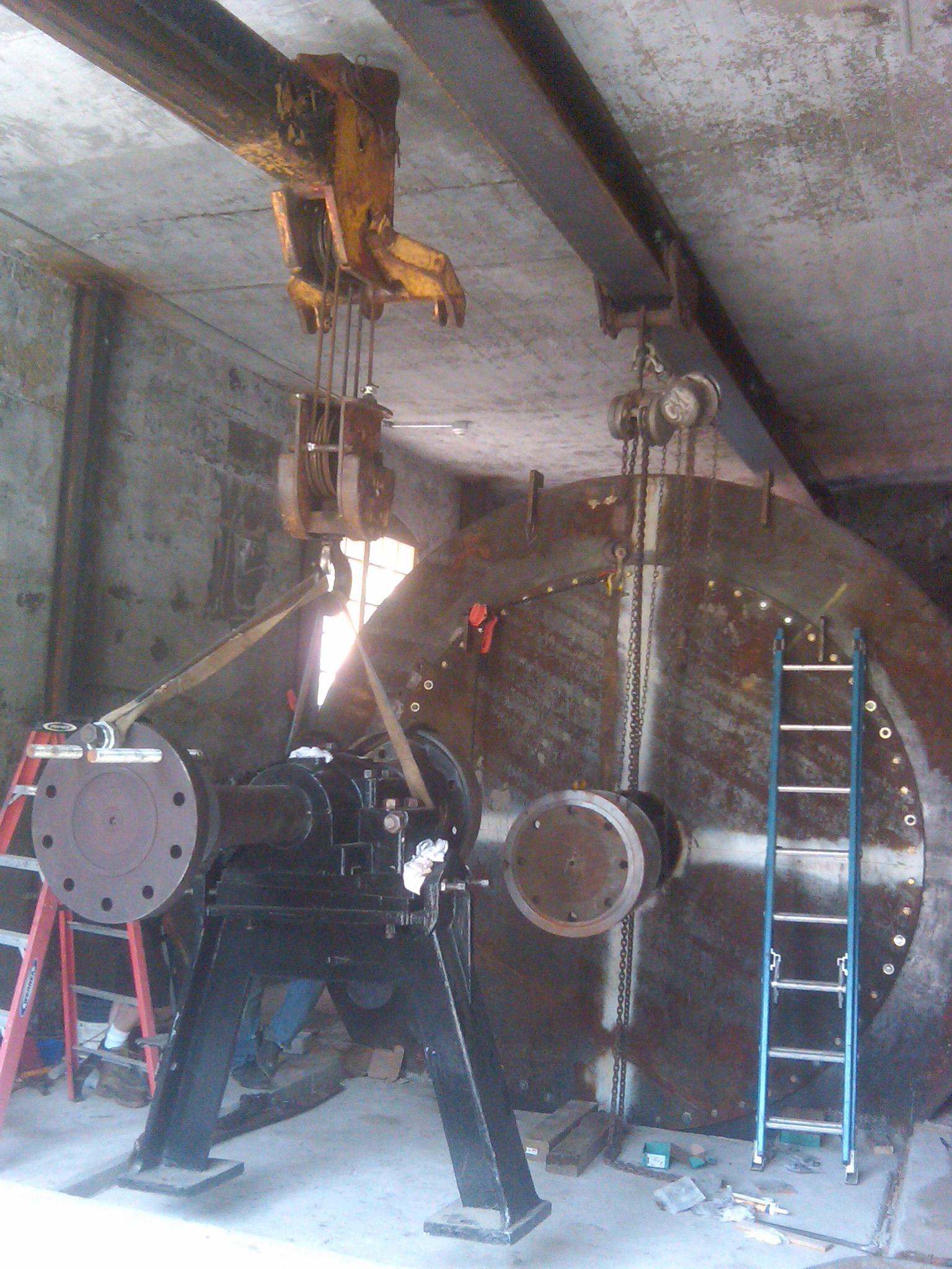
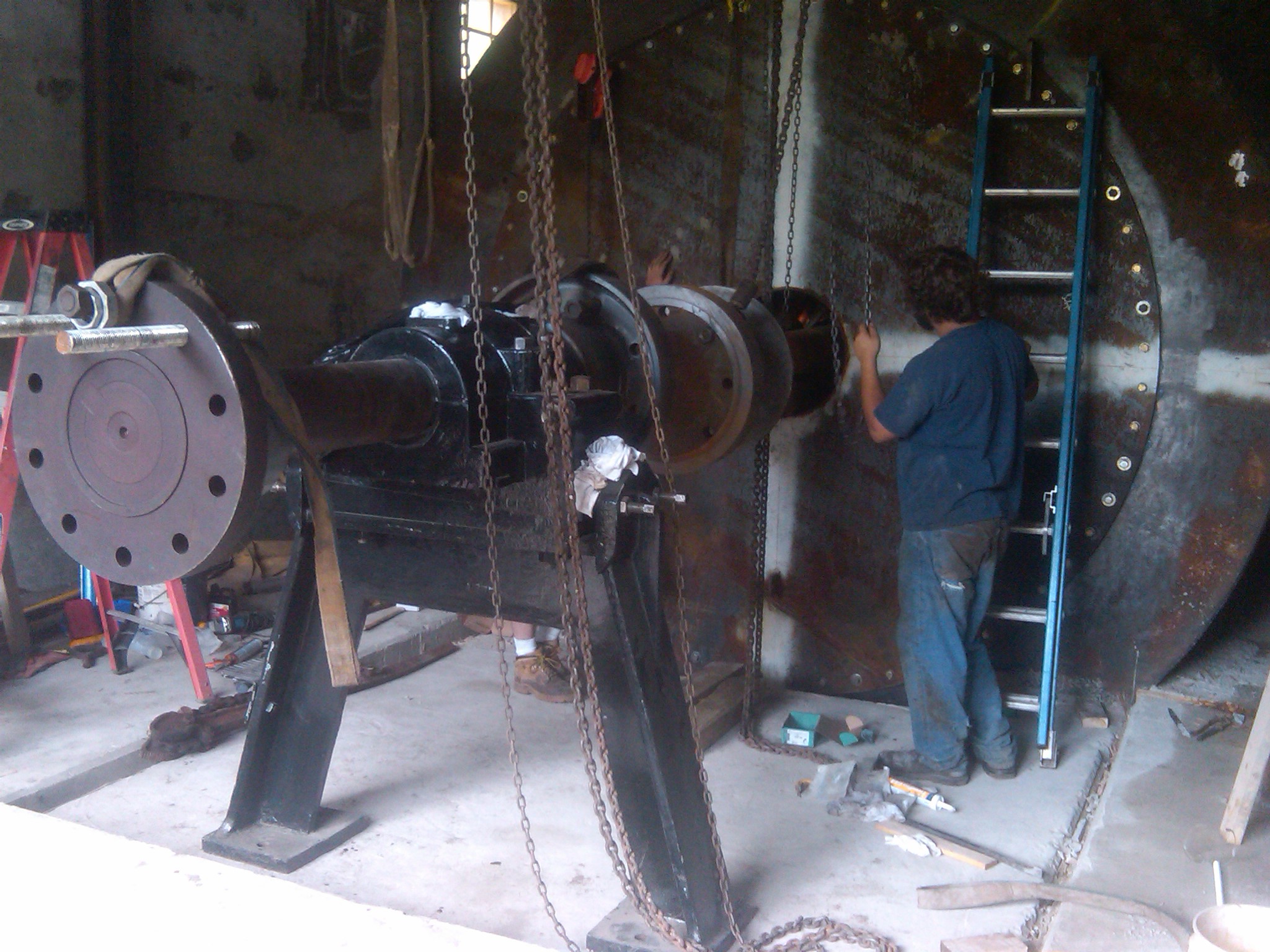
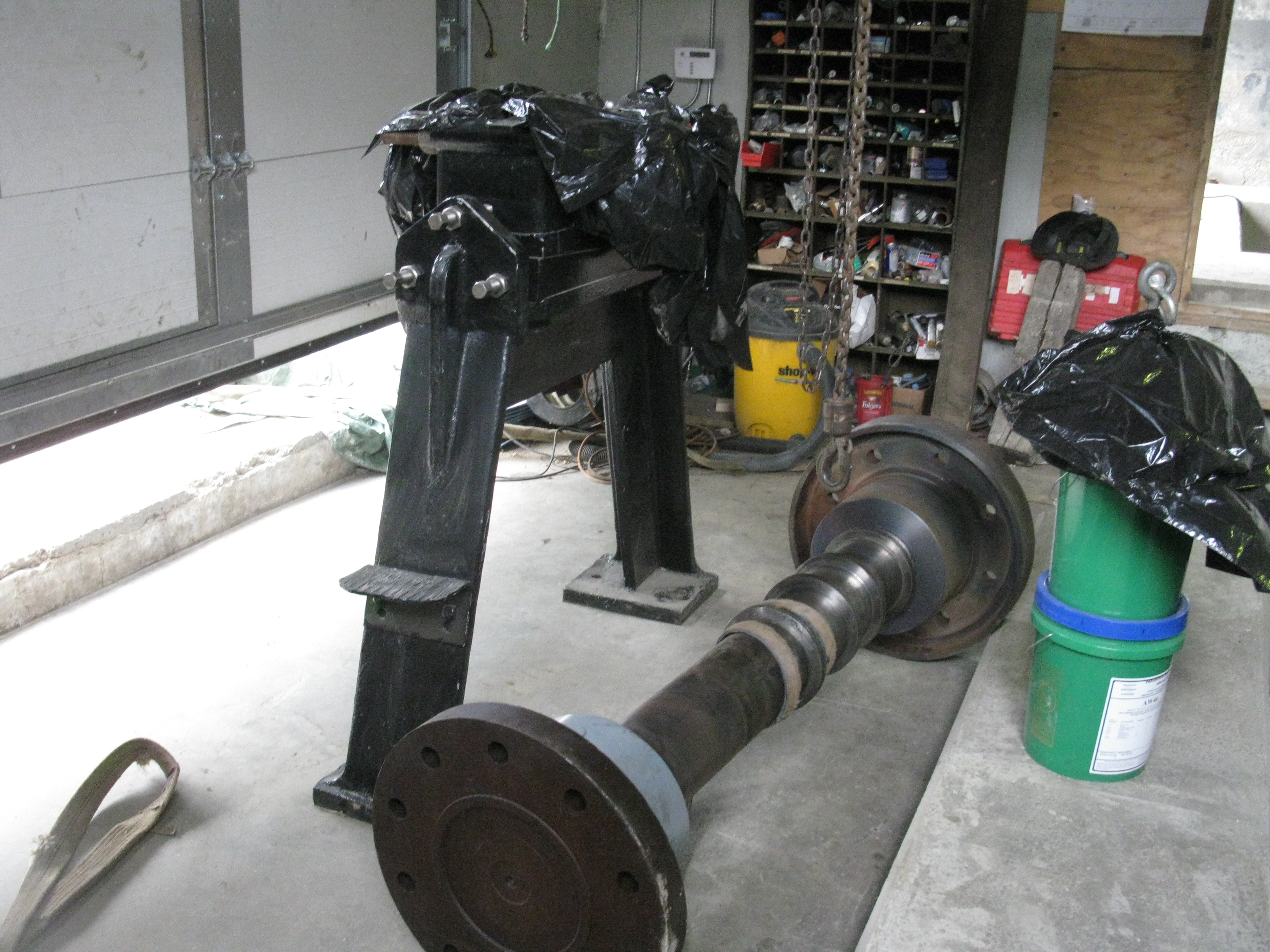
September 3rd, 2010, I have been restoring a Niles Boring Mill that can turn a 10 foot diameter object. The work has taken over a year since I purchased the machine from the scrappers. They damaged many pieces and many more pieces had to be replaced because they were worn out. It has consumed all my spare time. Please see the attached Picasa web album that details my efforts: http://picasaweb.google.com/frenchriverland/NilesBoringMillRebuild# August 30th, 2010, added Motors as Generators for Microhydro by Nigel Smith. August 21st, 2010, please see the youtube videos of tests of the Ishida & Service, "Linear Turbine" which Mr. John Service kindly submitted to me from Auckland, New Zealand. I included his e-mail verbatim in the sidebar link: August 19th, 2010, the editor of International Waterpower and Dam Engineering Magazine discovered frenchriverland.com and asked Will and Celeste to write an article on the small scale hydro renaissance that is sweeping the country. Here is a link to the article published in July's issue: Celeste\Water power magazine article July 2010.pdf Enjoy!!!
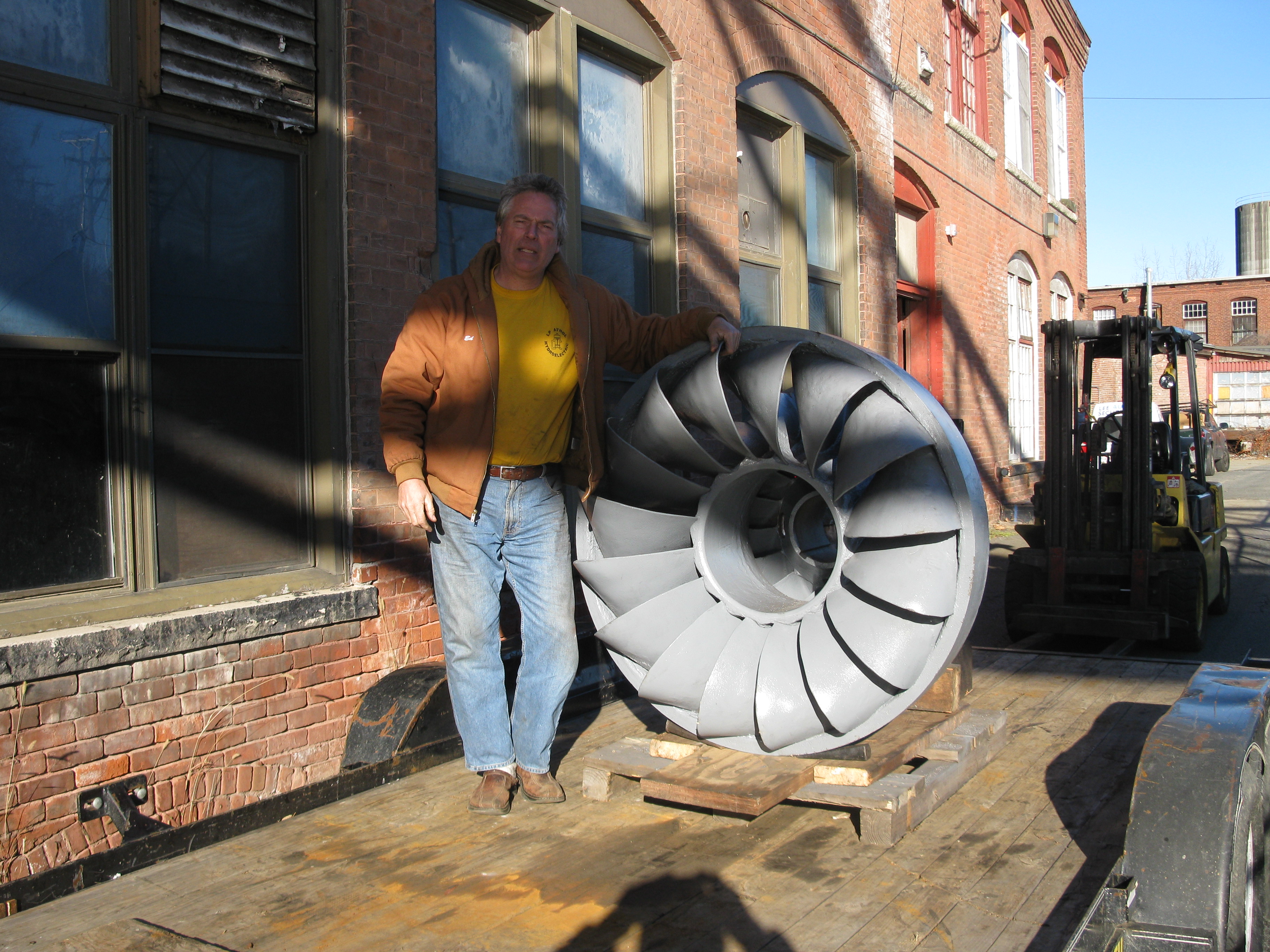
We are very excited! Our Leffel 18Z runner has just arrived from Bob and Ed Shannock's shop. It is a brand new runner and it is beautiful!!
Our crown plate and shift ring were damaged. Ed and Bob made a pattern and cast us new ones. We will have The Wizard machine the rough castings. We need both turbines ready for September 30th for our MTC grant.
Will and I spent this last weekend with Vern Towers, Bill Munch and John Remington pulling the little 18" Rodney Hunt Type 80 out of Avrill Park, NY. This is a terrible photo. I forgot my camera and had to use my Blackberry. Here we have finally gotten the gate case and runner loose. We are using a wire cum-a-long to pull it out of the remains of the pressure case. We placed a wooden beam from the top of the pressure casing to the top of the remains of the Woodward Governor to use as a lift point.
Will is passing our big wrecking torch to Vern Towers. Here we are removing the elbow halves to access the runner buckets.
Will is reaching beneath the gate case to burn off its mounting bolts
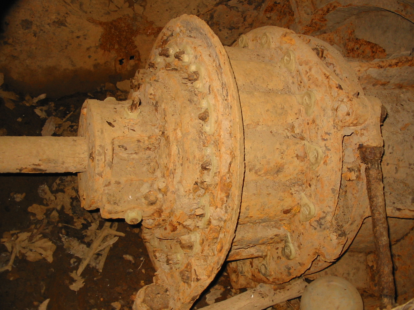
A view of the Avrill Park turbine before we removed it.
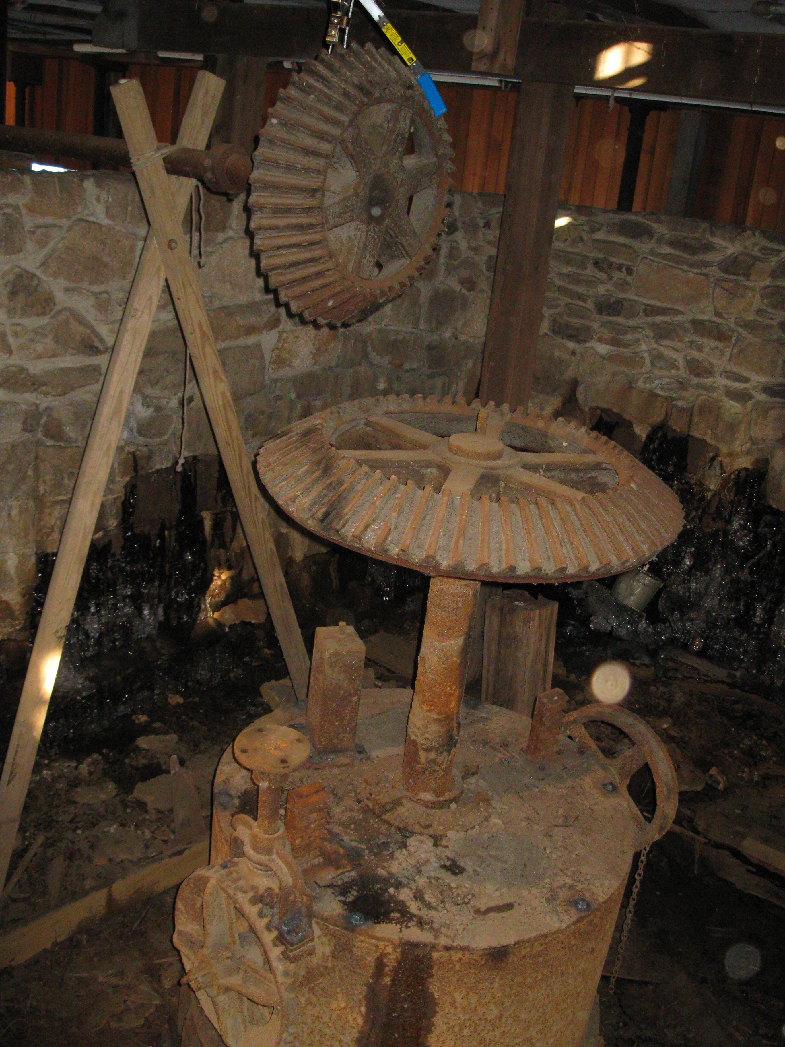
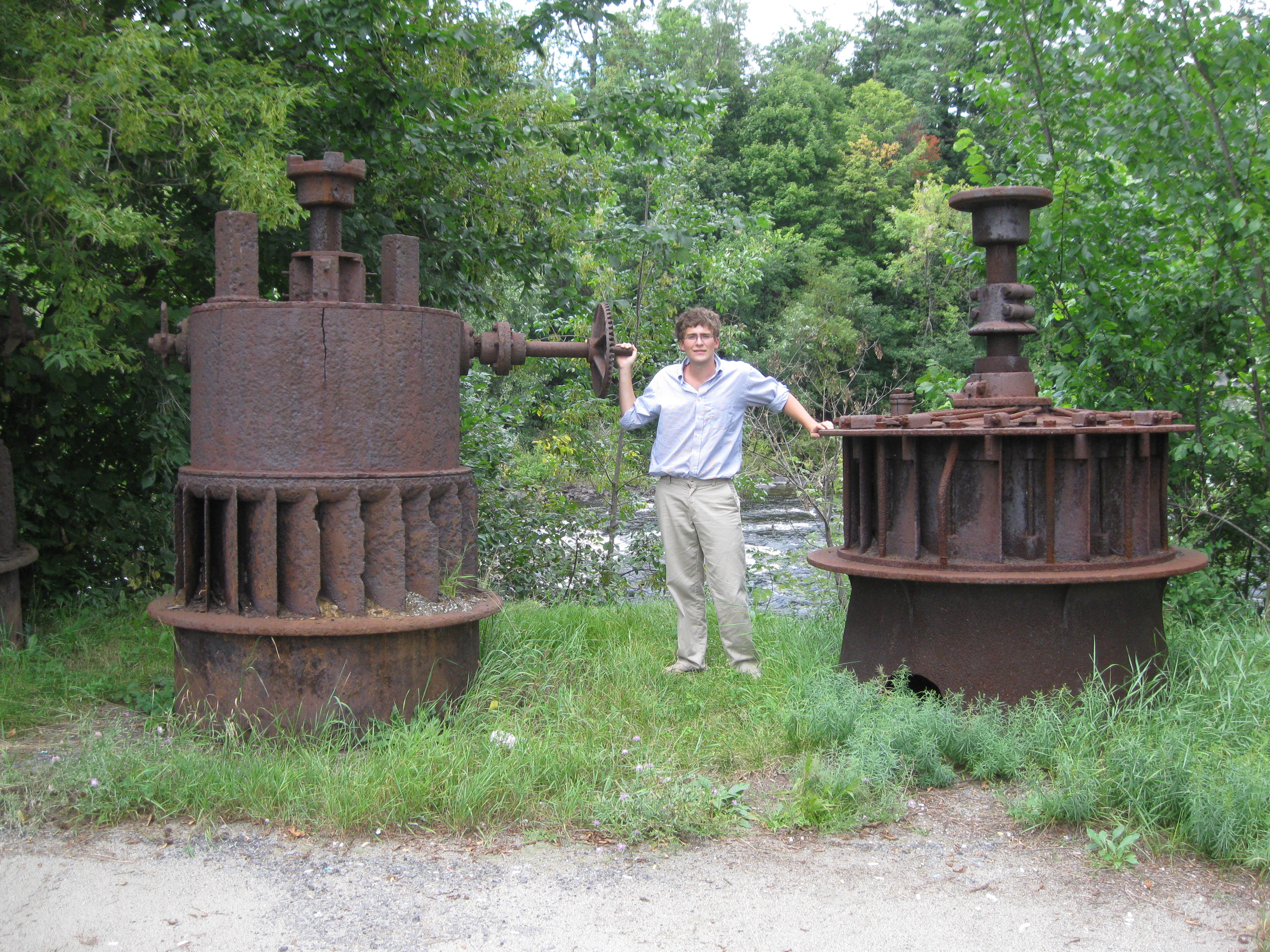
This is a classic Fourneyron turbine in the basement of Hal Slotnick's Mill in Holyoke, MA. Note the external vanes are actually the runner vanes. Note the rack and pinion system for opening and closing the cylinder gate.
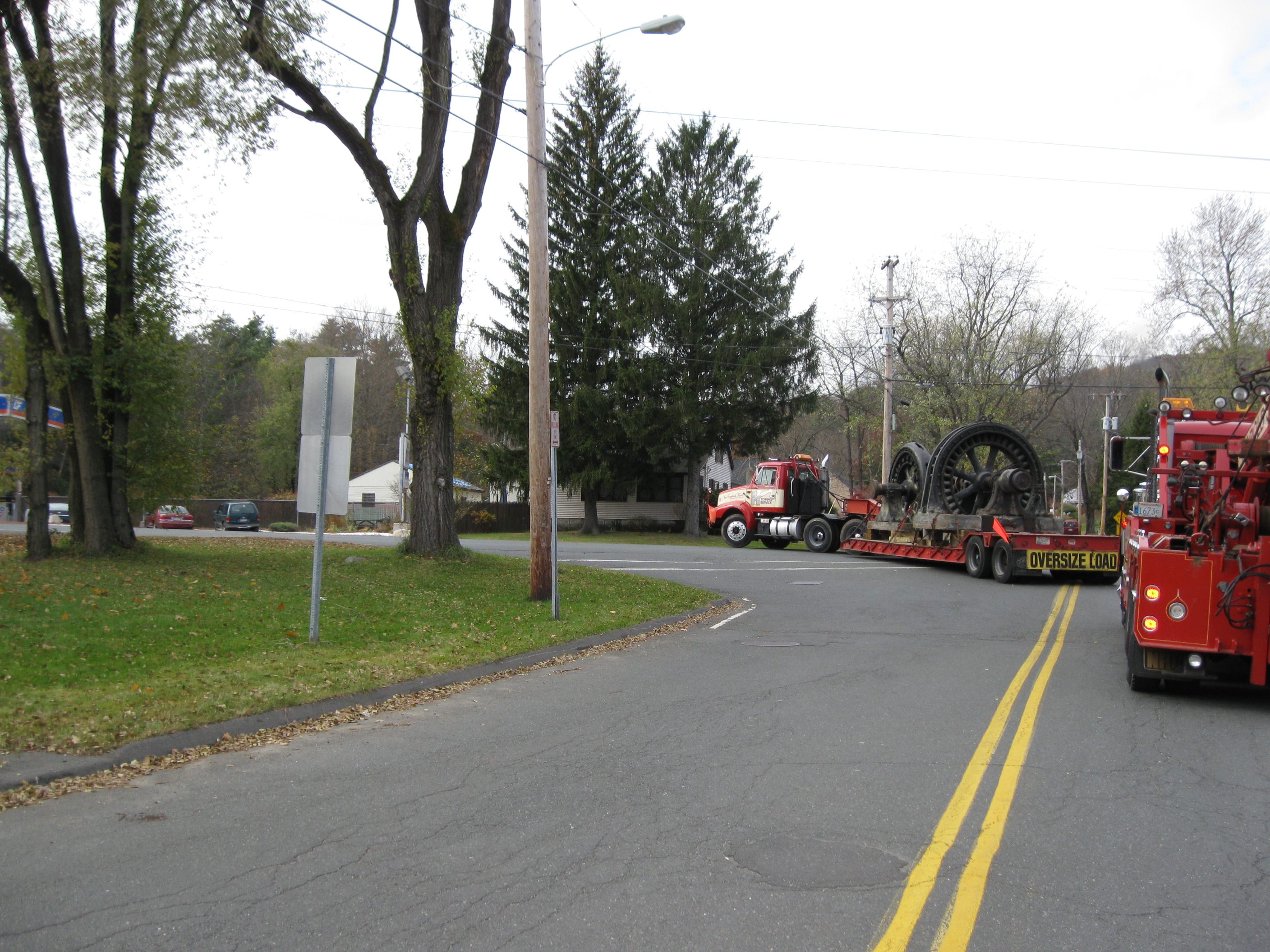
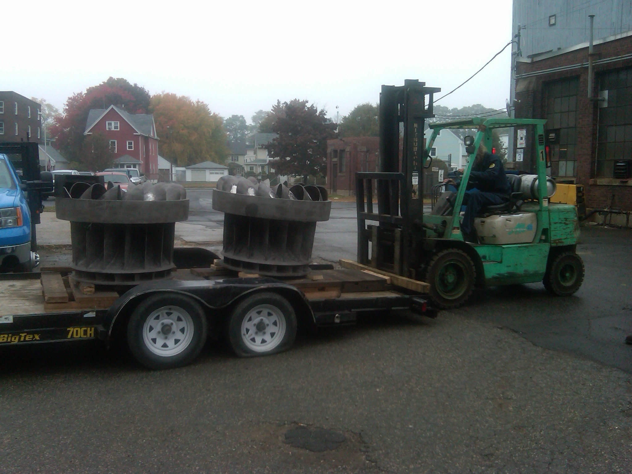
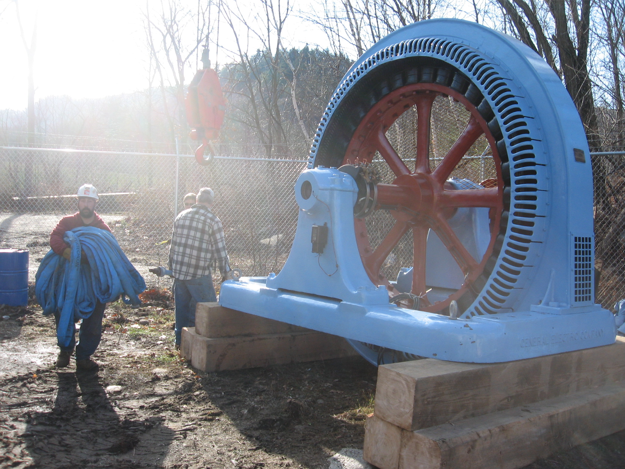
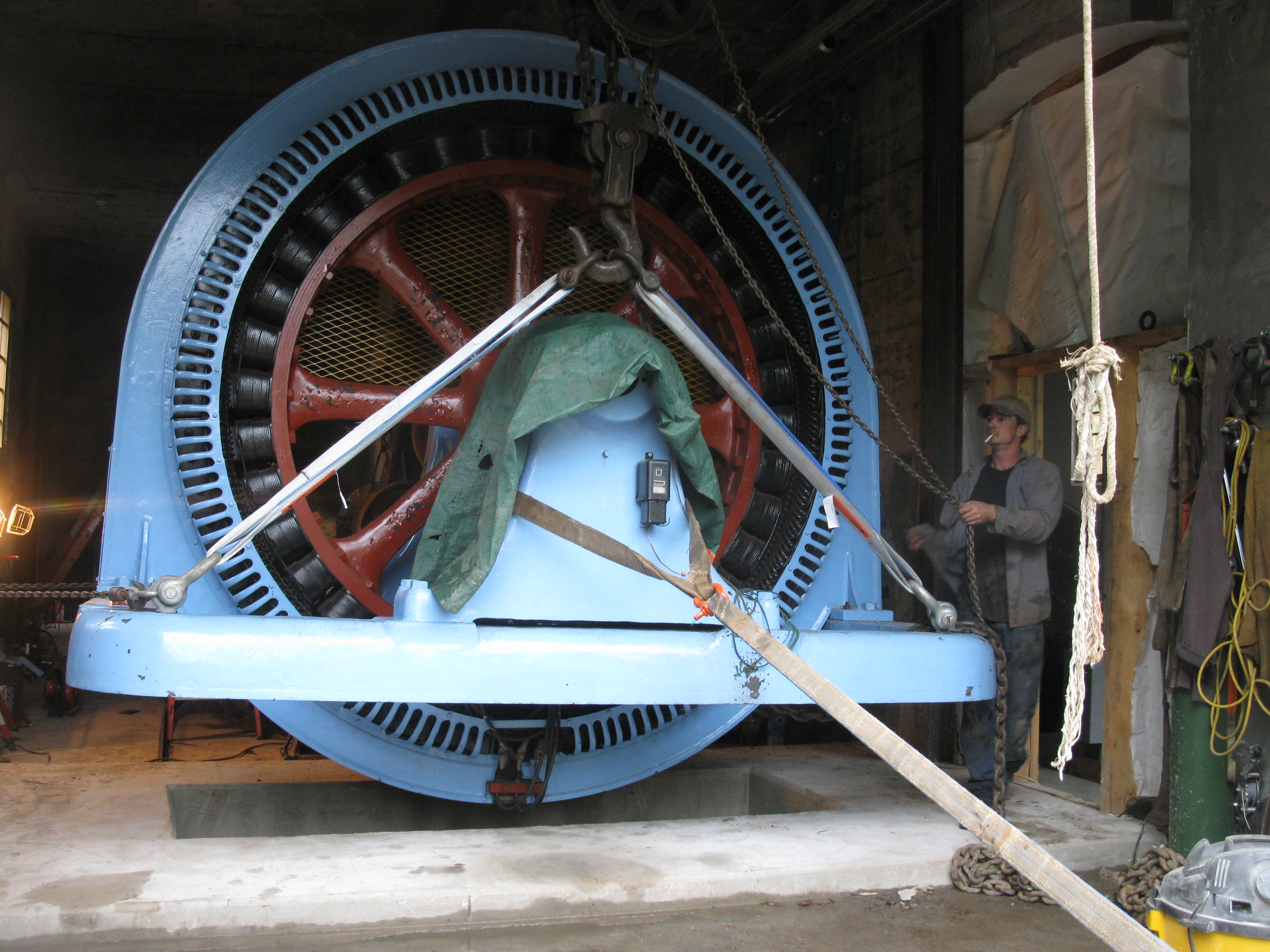
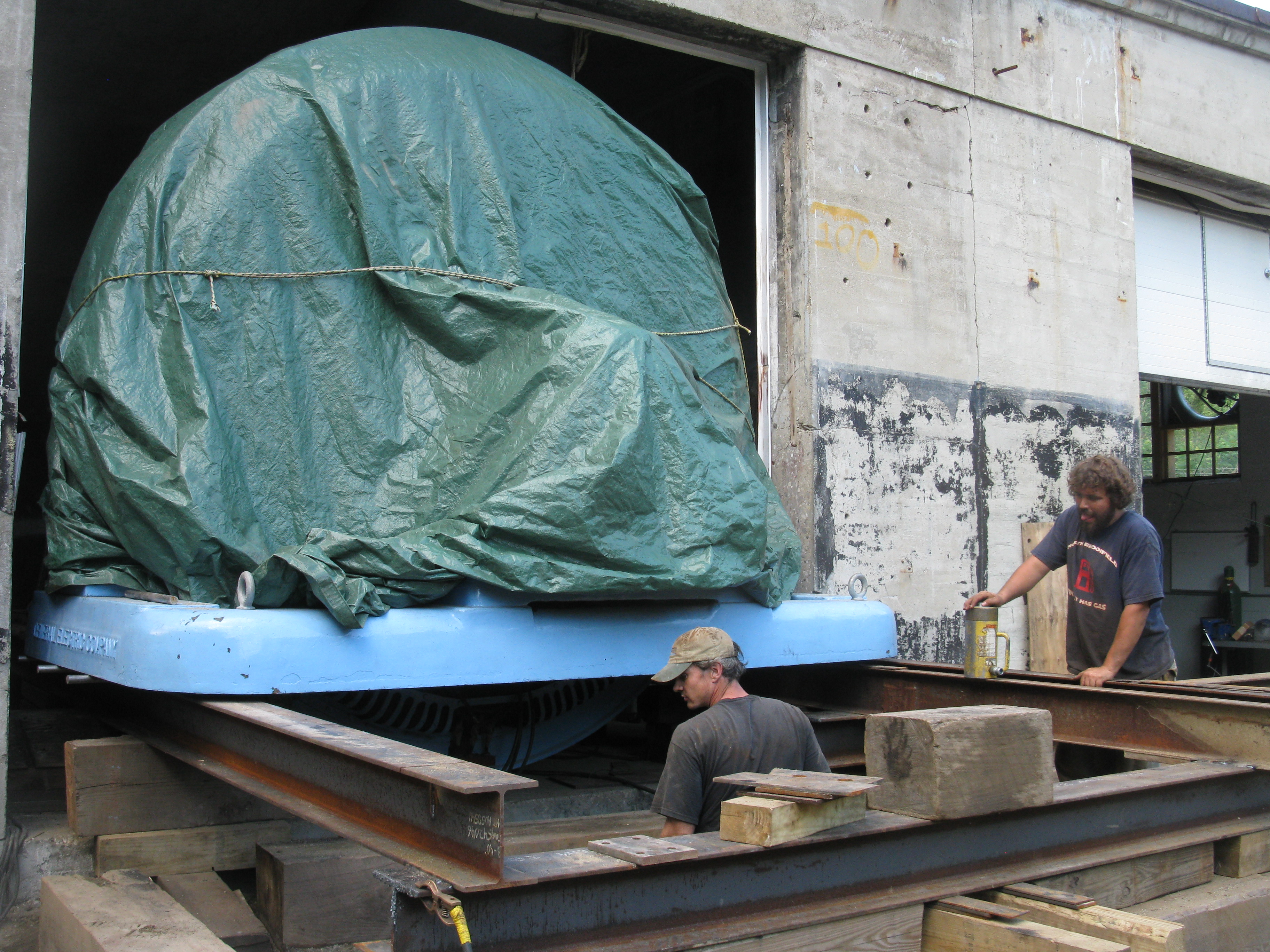
Two GE, waterwheel driven, synchronous, salient pole, generators going down the road on the same low boy. They are headed from Russell, Ma to dead storage in Athol, MA. There were numerous rubber neckers and double takes along the way!! Nov 5th, 2009, Moving the Synchronous Hydro Generators to dead storage, click on the following link!!http://picasaweb.google.com/frenchriverland/MovingRussellGeneratorsToDeadStorage# . Here is the No. One Generator being loaded onto the ramp truck. They are being trucked to LP Athol to be dry stored. Will & Celesty are installing these units at a new hydrostation they just purchased. Indian River\Indian_river_Article[1].pdf<<< News Article about our Indian River Plant. Click here!! October 6th, 2009; Added Smith Bulletin 110
September 23, 2009, For a progress report on the 120 inch Niles Boring Mill, please see:Picasa Web Albums - William - Niles Boring ...
******September 2nd, 2009. Added Will's WPI, IQP, Thesis,
"Hydrokinetic Energy in Massachusetts".<<<< This paper
is going to become a classic!!! This is a really big file. It
takes time to load, but it does eventually appear! Please be
patient, its worth it!!!******
|
|
October
11th, 2011, added "Water Turbines; Contributions To Their Study,
Computation And Design" by Professor S. J. Zowski. This is a
great paper by one of the leading turbine designers of his time.
Zowski invented the high speed runner with his "Free Whirl
Zone". These runners included the Morgan Smith "S", the Rodney
Hunt Type "105", and the Leffel "Z" and Leffel "S" runners. They
were characterized by a bell shape where the crown of the runner
was approximately 1/2 the diameter of the skirt ring. The
specific speed in English Units varied from 100 to 105. October 11th, 2011, added design notes and powerhouse reinforced concrete calculations for the Natick Dam HEP. August 21st, 2011, we finally got the second unit into commercial operation. We are finalizing the downstream fish passages and doing cosmetic duties.
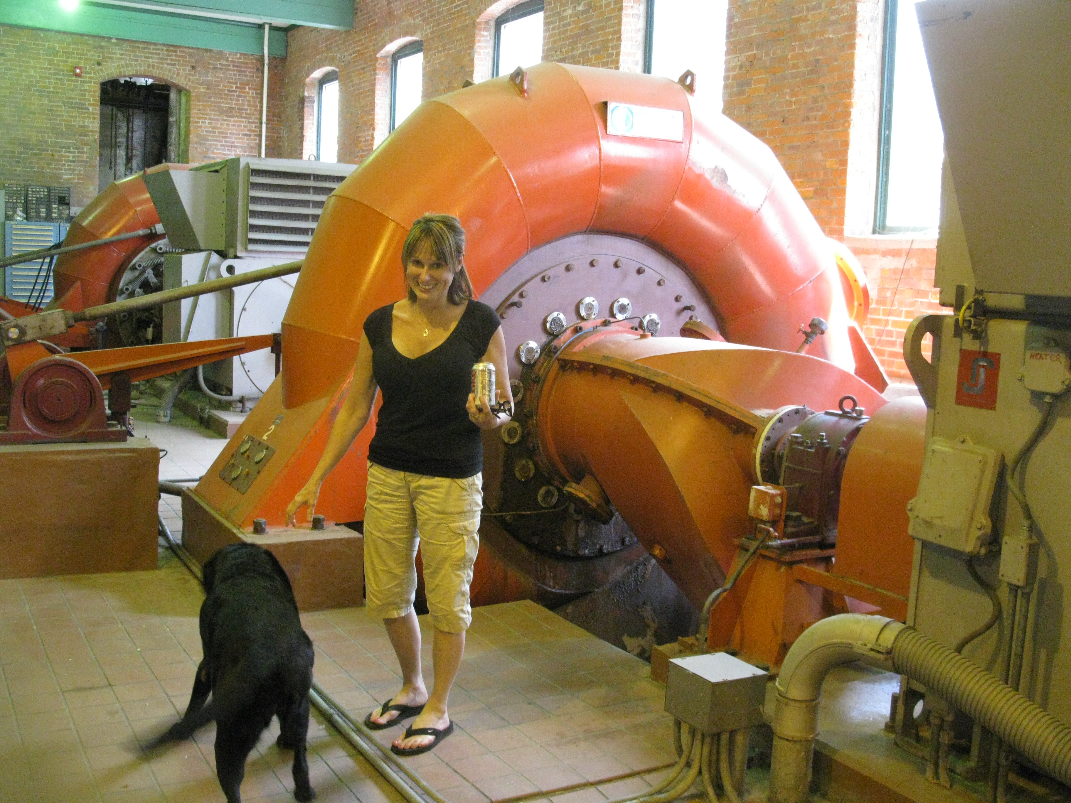
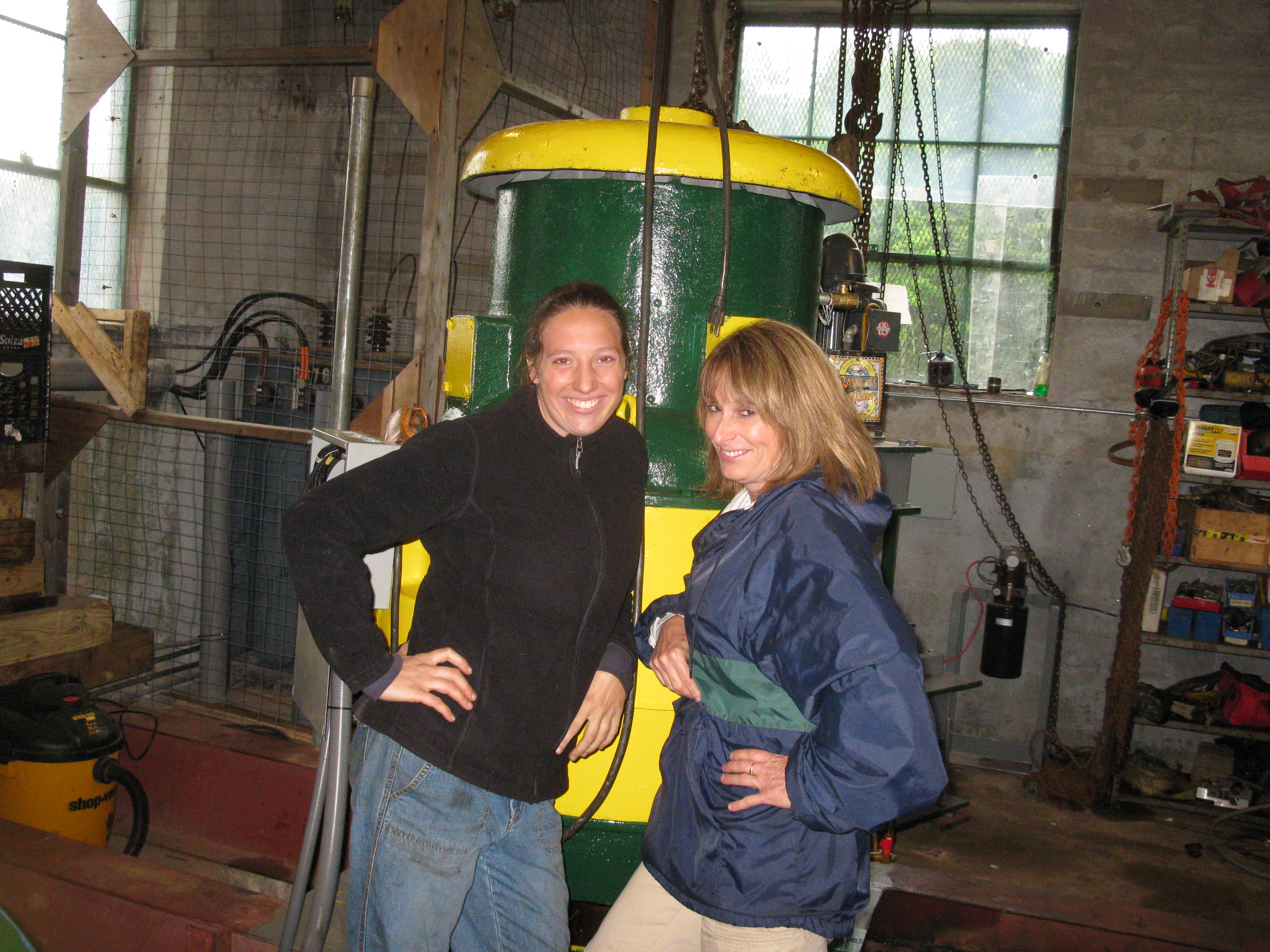
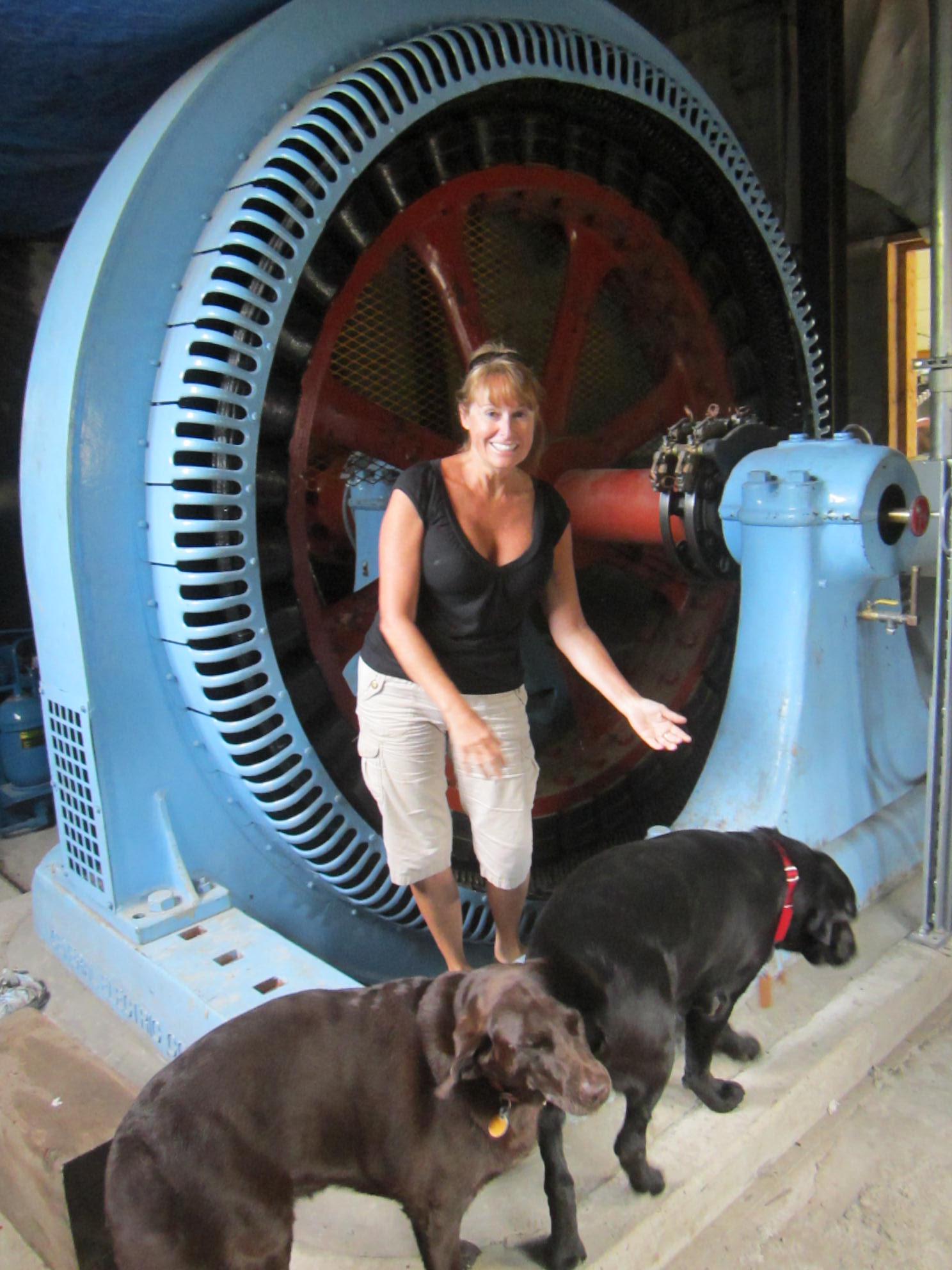
Karen, Cleo and Tut in front of the finished No.One Unit's salient pole generator.
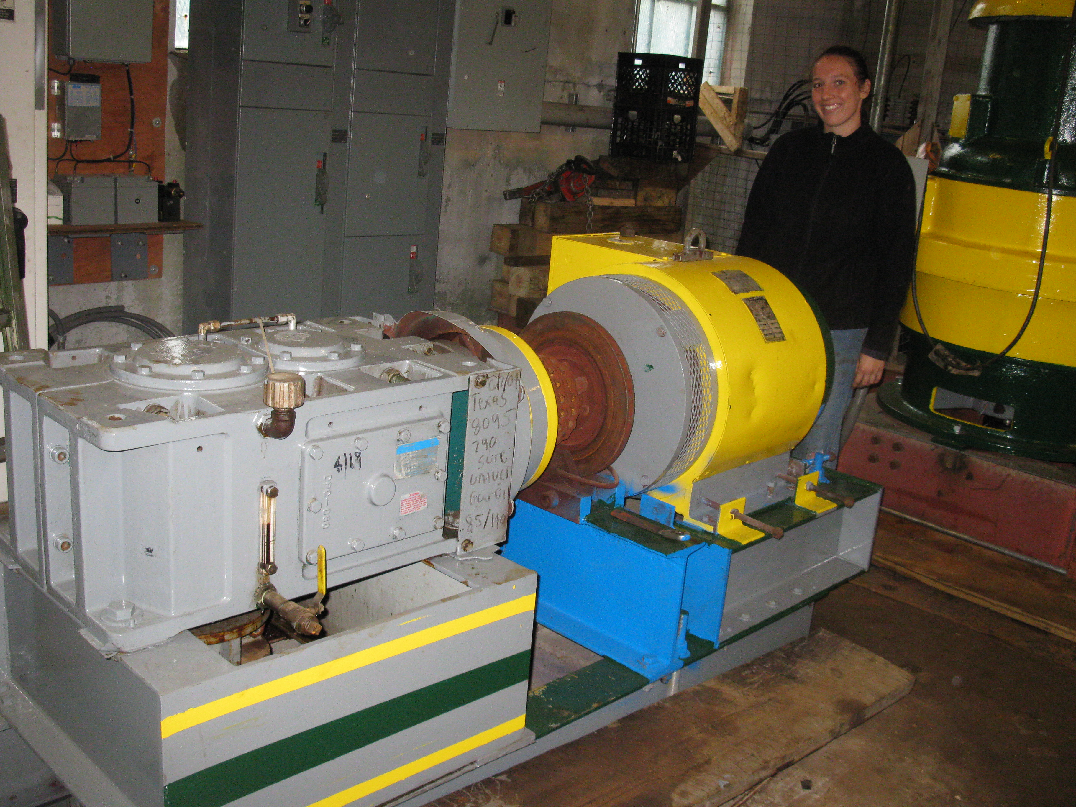
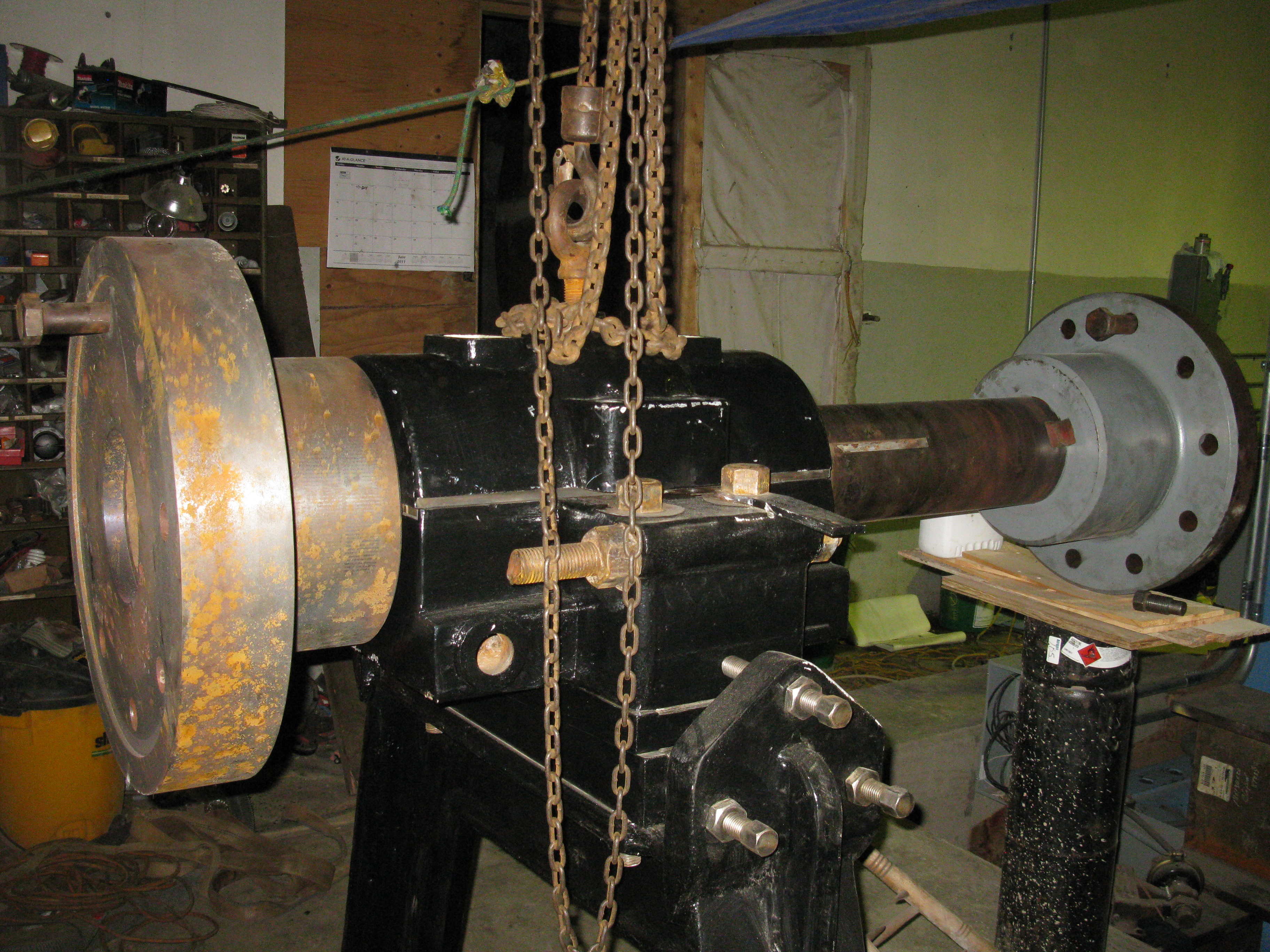
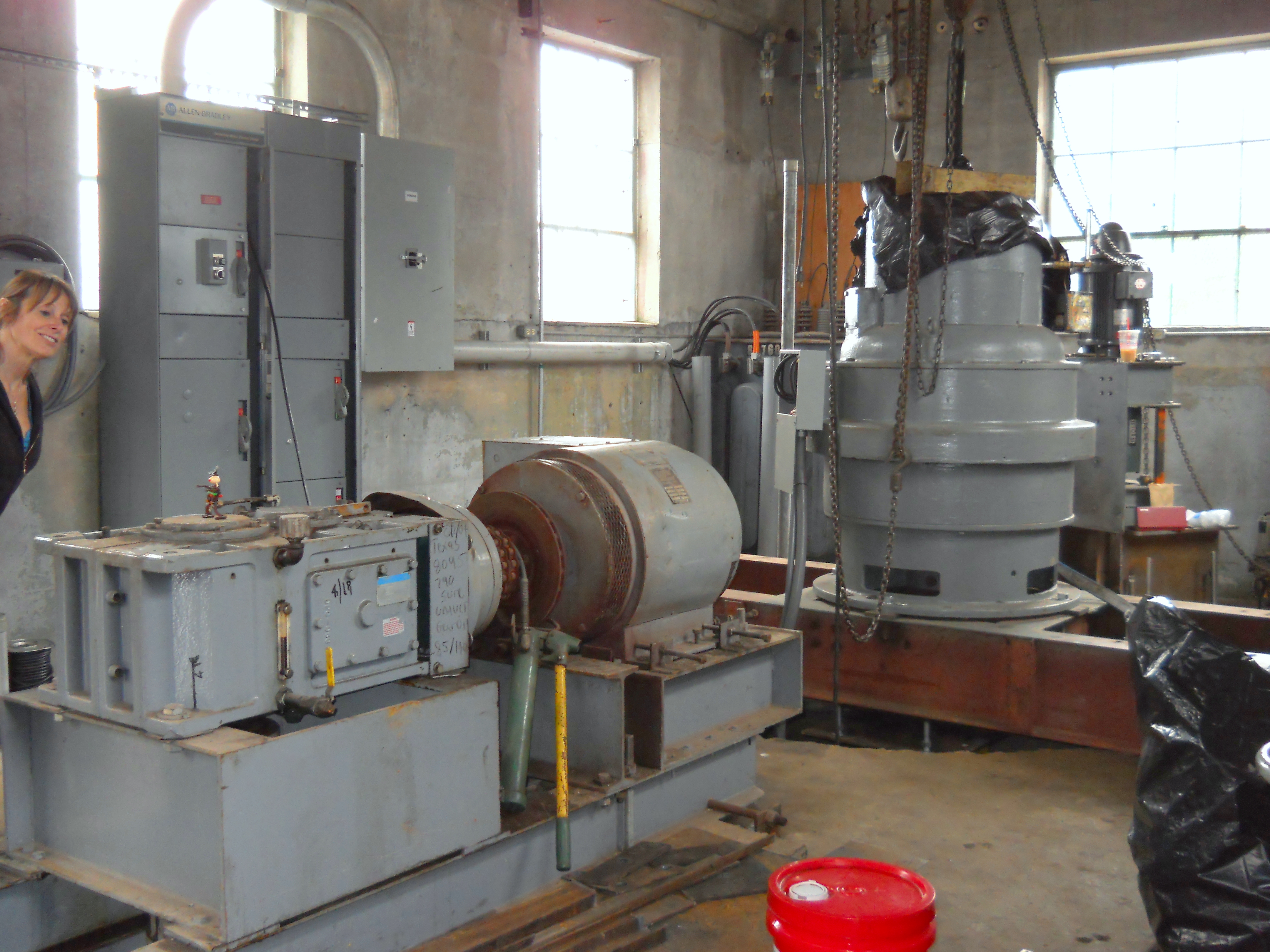
Karen and Tut in front of the new No. One pressure casing. Note the thrust stand, new couplings and disc brake rotor behind her. Note the new Sorenson hydraulic power pack. The blue cylinder is a hydraulic accumulator 1/2 filled with nitrogen gas and 1/2 filled with pressurized oil. In the event of an emergency shutdown the gas pushes the oil through an electric dump valve and forces the hydraulic cylinder to close the turbine. The dump valve is closed by electricity. If the power fails it opens up to close the unit down.
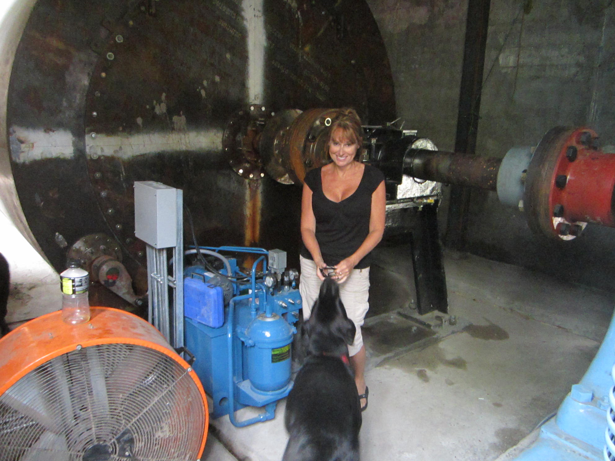
Karen and Cleo in front of the running No. Two unit. Notice the brown primer on the side of the pressure tank. We are starting our final painting process. We love the baby blue brightwork! July 27th, 2011, added, "The Hydraucone Regainer, Its Development and Application In Hydroelectric Plants", aka: White Hydraucone. This is one of the most venal exchanges, between the two foremost hydraulic engineers of the last century, that ever played out in the Transactions of the Society of Mechanical Engineers!!!
The up
shot of all the brouhaha is that curiously, both designs
worked exceedingly well!! They were also very expensive.
White's theory was that the easiest way to turn a jet was to
impinge it on a flat plate. Moody thought that was ludicrous
and you would lose tremendous amounts of energy. Moody
thought you could eliminate rotational core losses by having
the solid uprising cone preventing anti rotational vortices.
White thought that was ludicrous and the secondary uprising
cone would produce huge friction losses. So it was an
unpleasant surprise to both of them, when TVA model tested
and installed both prototype draft tubes, and got recovery
efficiencies greater then 94 %.
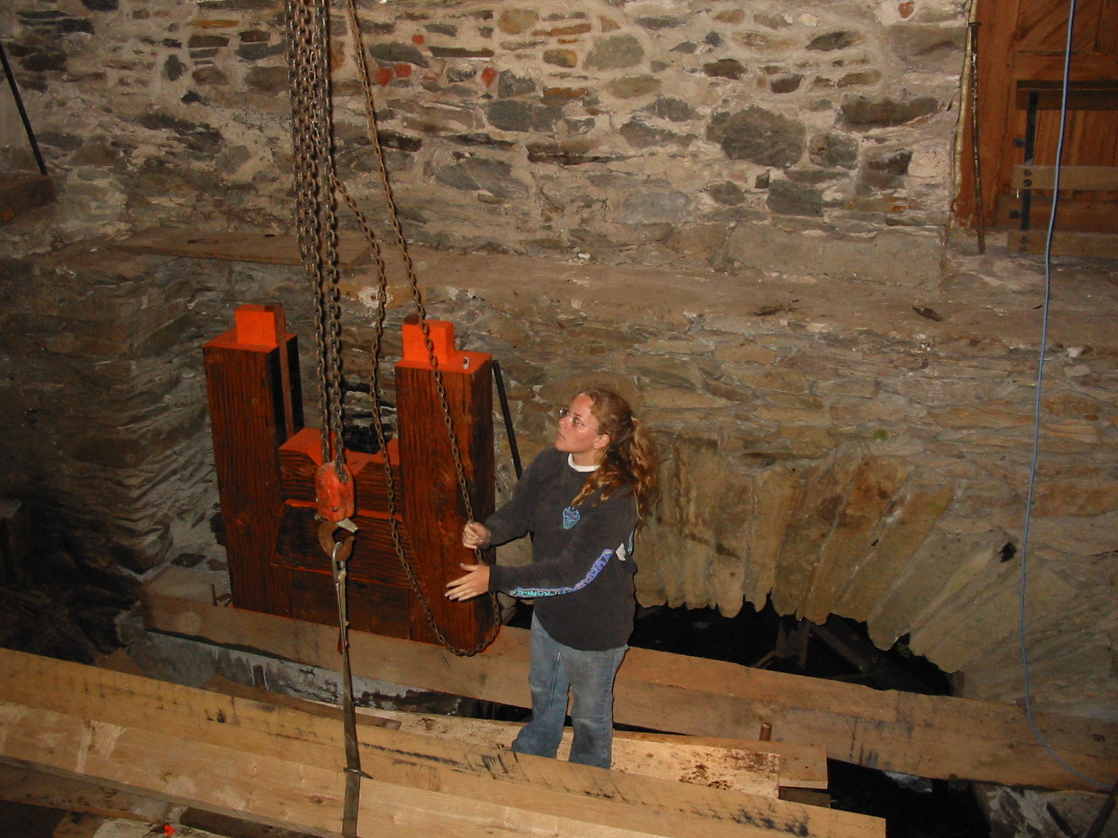
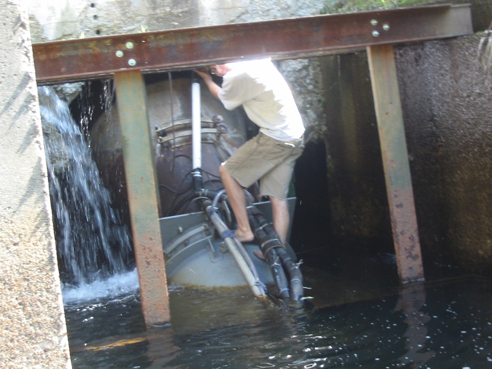
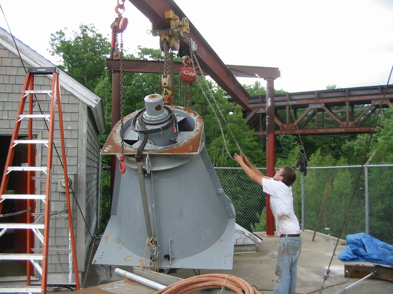
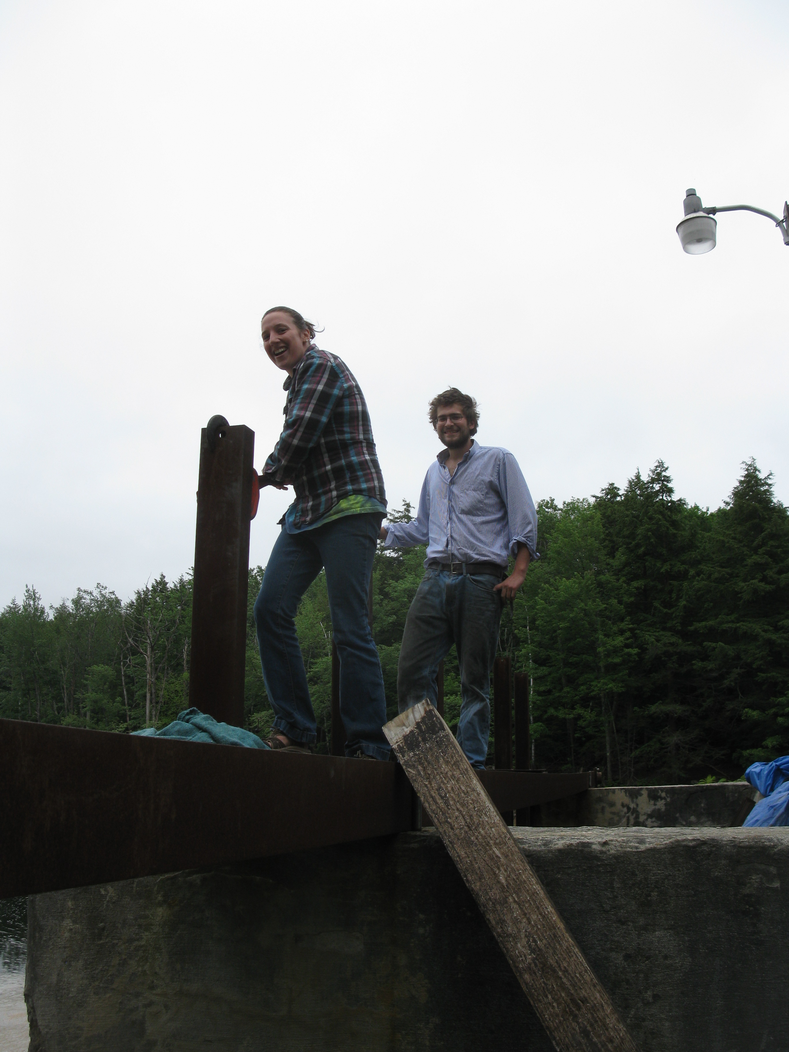
Maura Hennessey and Will Fay removing stop logs in the forebay at Tannery Pond. The waterbox had been empty for two years while Will replaced the trash racks and installed Units Two and Three. When Davis and I installed this 36 inch main carrying beam, and the vertical stop log channels, back in 1994, we installed them in front of the trash racks. This allows the racks to be replaced without draining Tannery Pond. Will and Maura started rock climbing last year. They have become quite strong!! It makes it easy to work the chain cum-a-long to pull the stop log panels.
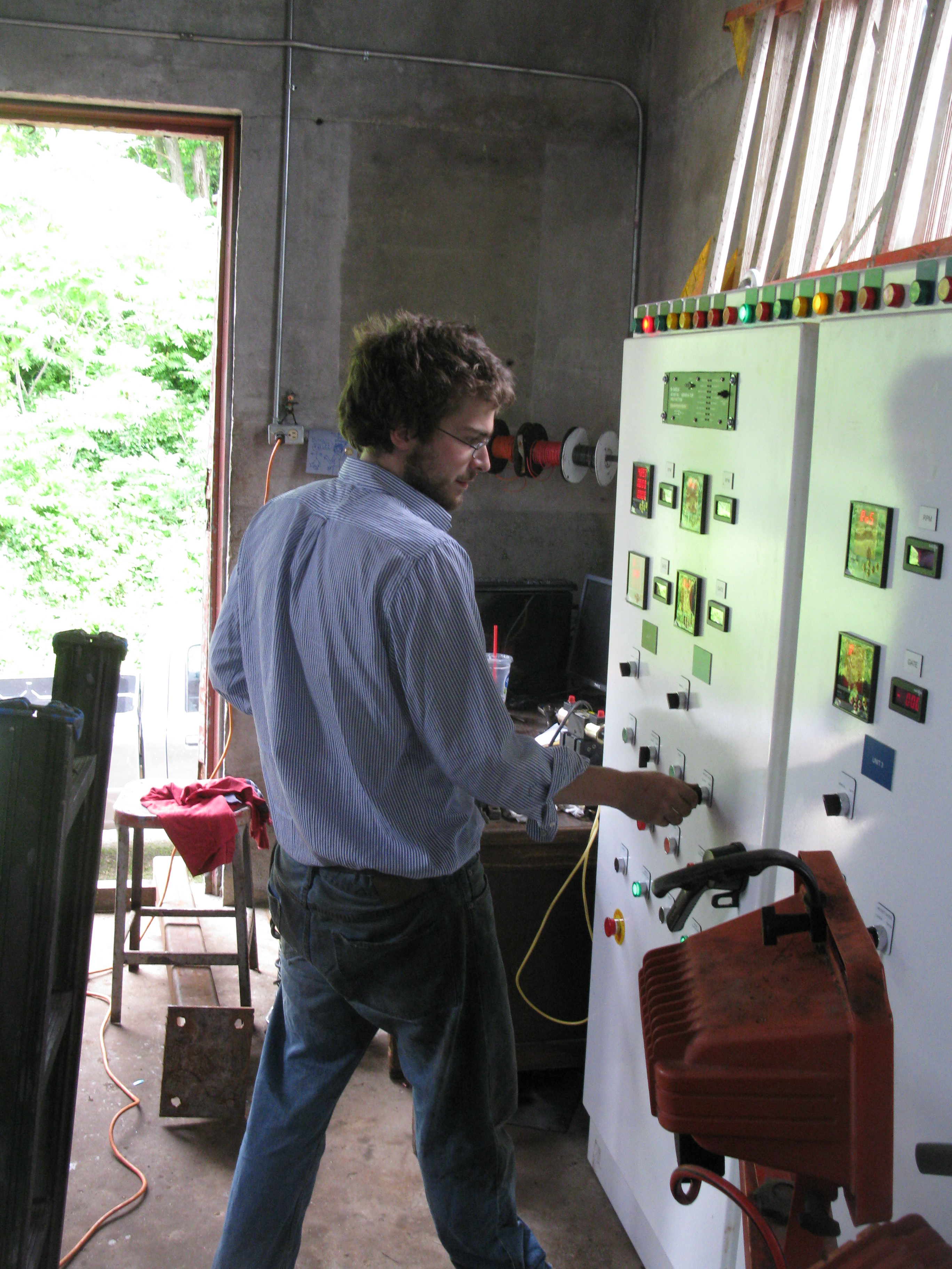
Hi everybody, Will has energized Tannery Pond Unit Two for the first time! Here I have caught the drama of him throwing the breaker in!! Congratulations Will!!!!! It has been a long, productive and educational road!!
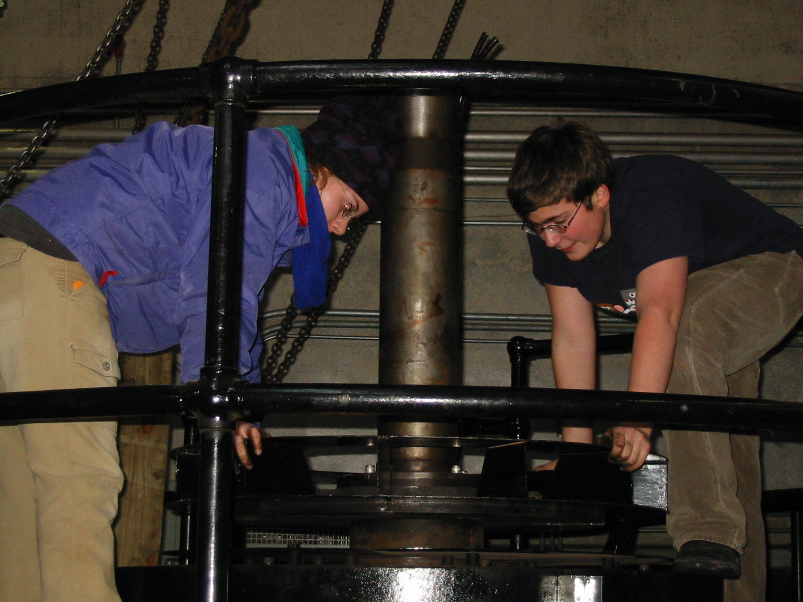
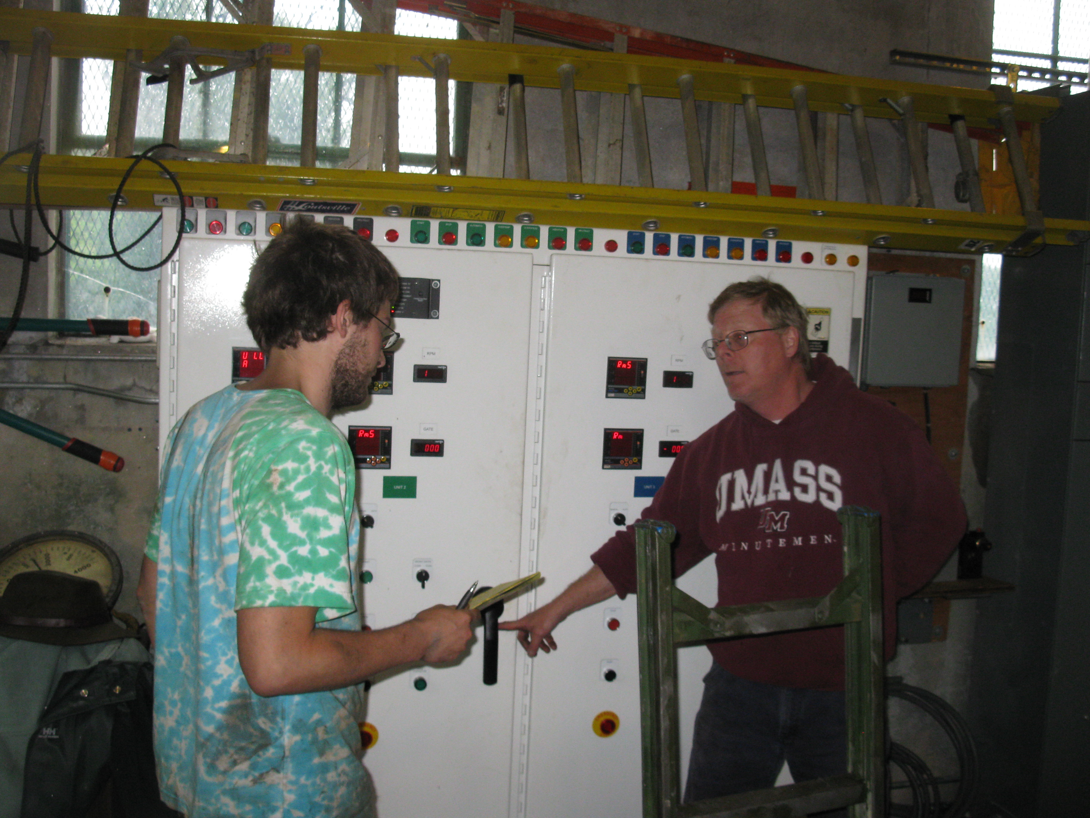
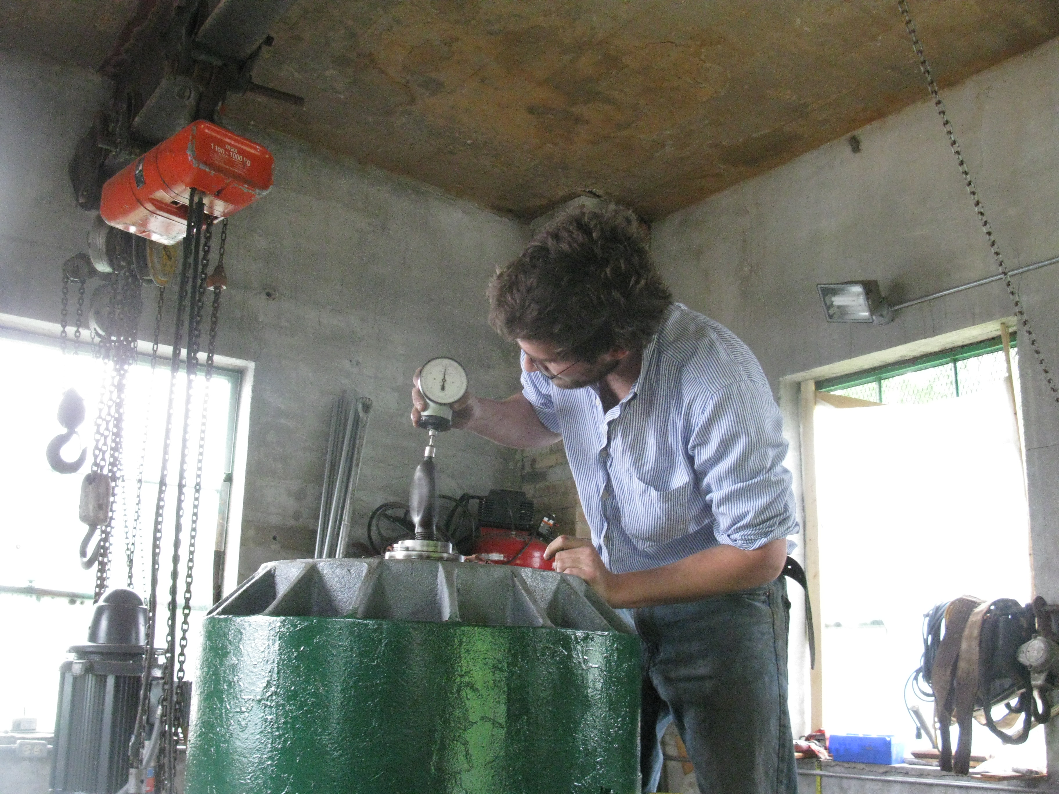
Will is determining the speed of Unit Two to allow for a soft start. The digital tachometer was not wired up yet so he used my father's Biddle tachometer. He had to catch the center of the spinning I- bolt.
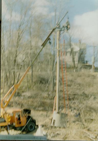
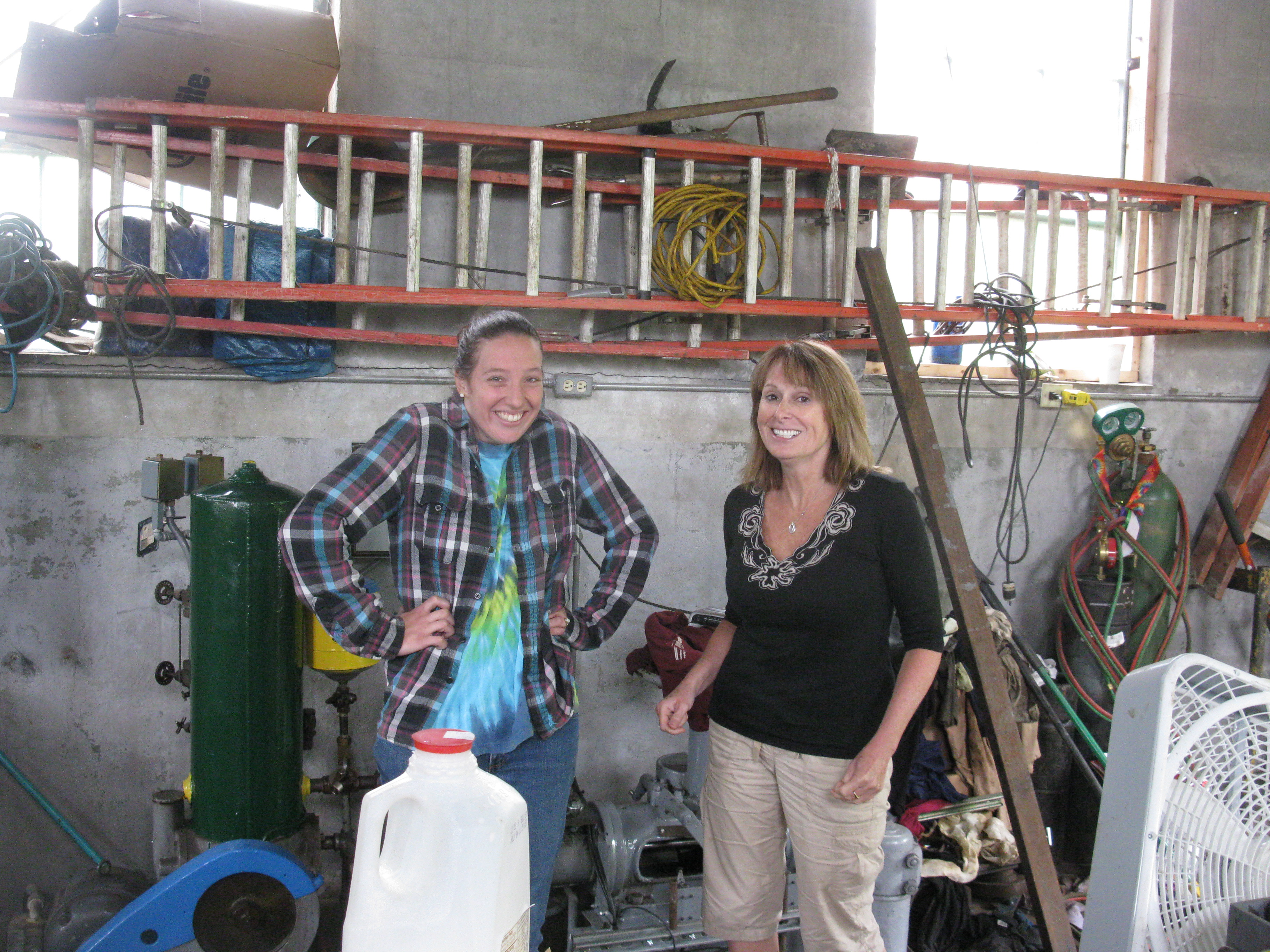
The supervisor girls are ecstatic!!!! June 21st, 2011, on Thursday and Friday we lowered the No. One generator onto its new pedestal. I trucked the new governor shaft to the site. Yesterday, Industrial steel and Boiler arrived with the new eccentric, off set cone that connects the new 8 foot diameter penstock to the new 13' diameter pressure casing. It came in 4 pieces so that two men could assemble it. Cole used the little Galion all terrain crane to swing the pieces into place. Our pedestal was too close to the pressure casing by 8 inches. Warren is turning the 8 inch main shaft to adjust its length. Here is a new Picasa Web album: https://picasaweb.google.com/frenchriverland/MovingNumberOneGeneratorIntoPowerhouseII#
Will Fay and beautiful Maura Hennessey in front of the newly finished No. 3 Unit at Tannery Pond. It is so difficult to wash Never-Seize from your hands!!!!
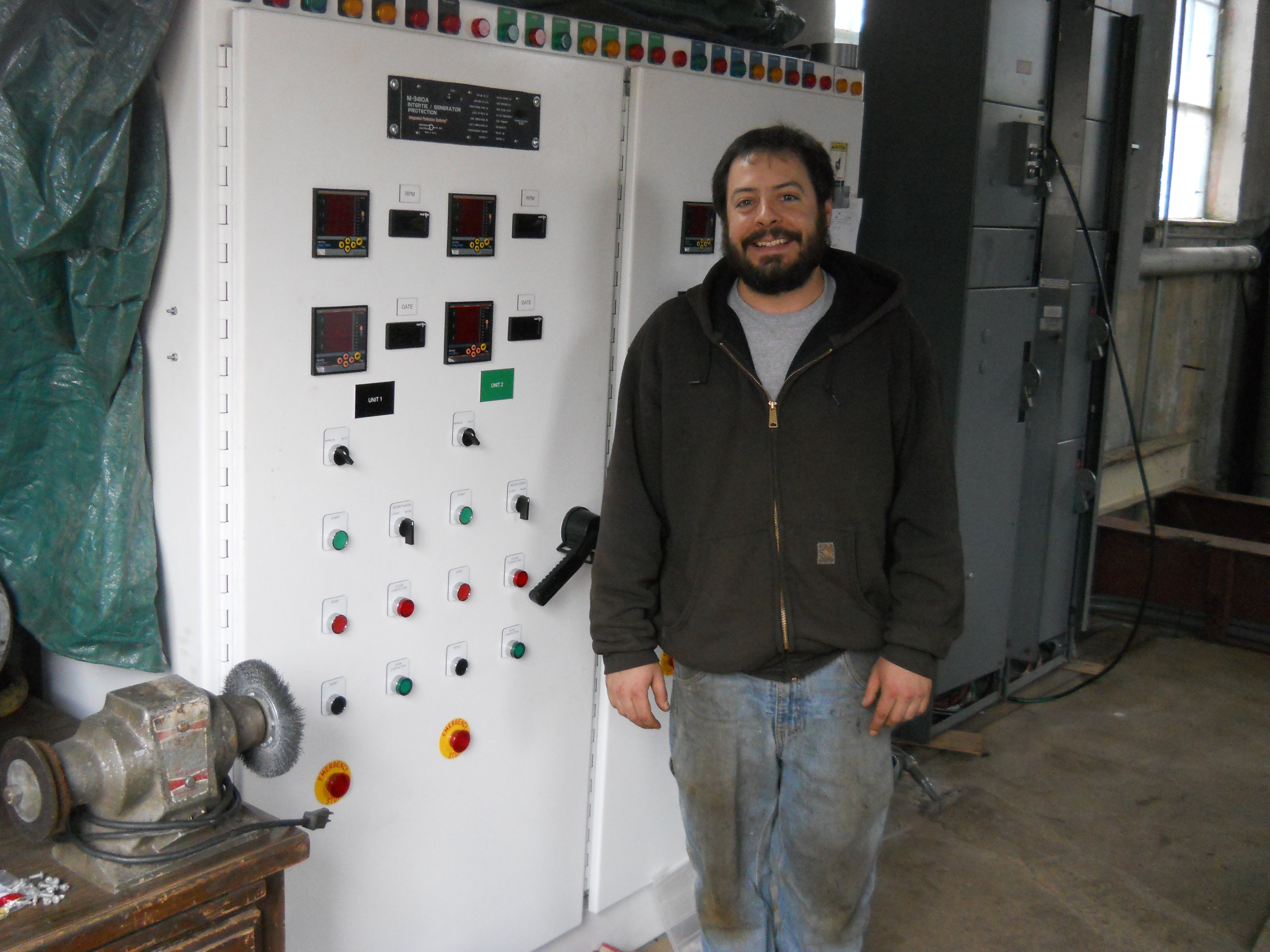
Karen Westerman and Marshall Smith gaze in wonder at the newly installed switchgear at Tannery Pond HEP. Note the elaborate, large port, valve stack Marshall and Will installed on the Woodward Governor. They previously removed the flyball head to be able to install the four way valve. The valve is actuated by electric solenoids. The solenoids will be controlled by the Allen Bradley, SLC 500, programable logic controller.
The newly completed No. Two unit at Tannery Pond HEP. Note all the details. Will Fay has designed, Auto Caded, machined, rigged in and installed the Main shaft, main shaft 1/2 couplings, shift arm turn buckle arms, governor shaft, governor shaft foot bearing, lignum vitae quarter blocks, nose bolts, eccentric pins, wicket gate pins, finished wicket gates, tie rod ends, tie rod bolts and wicket gate links. He has become and outstanding civil and mechanical engineer, machinist, business man and entrepreneur!!!!
Will and I posing for Karen in front of the No. 2 Unit at Tannery Pond HEP.
April 25th, 2011, here, Marshall Smith of Smith Alternative Energy (www.smithtest.com) proudly poses in front of the newly installed switchgear for Tannery Pond HEP, on the Millers River, in Winchendon, MA. In the background is the newly installed generator control center. Marshall, his father, Ken Smith P.E. and his brother Ian Smith have designed and installed the electrical controls. It has been a trying process as they have also concurrently been designing and installing the control system for our Indian River HEP on the Westfield River, in Russell, MA. Three Allen Bradley SLC 500 PLCs automatically control the three TG sets. A continuous record of headwater, tailwater and bypass reach water levels is made for FERC verification.
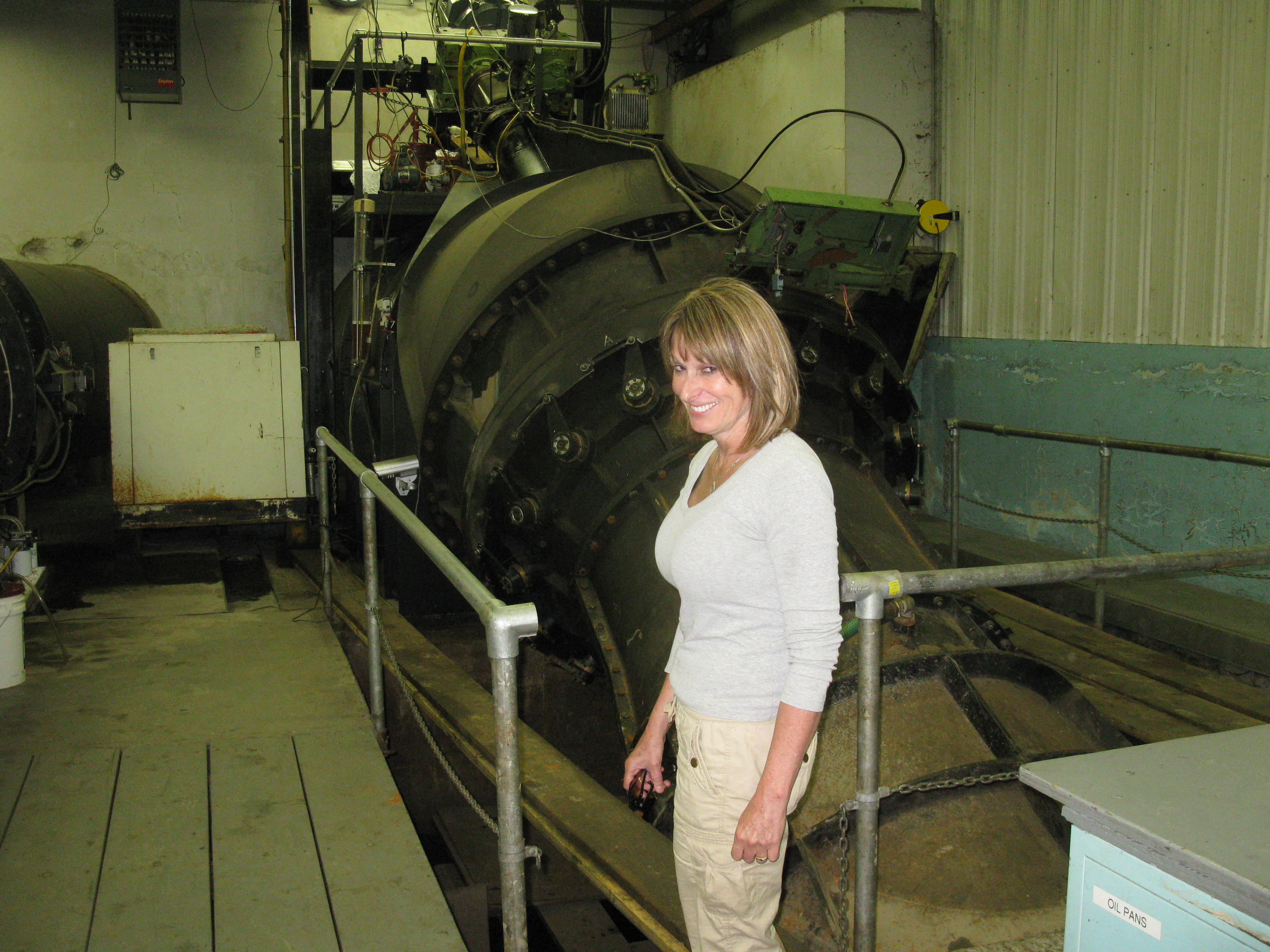
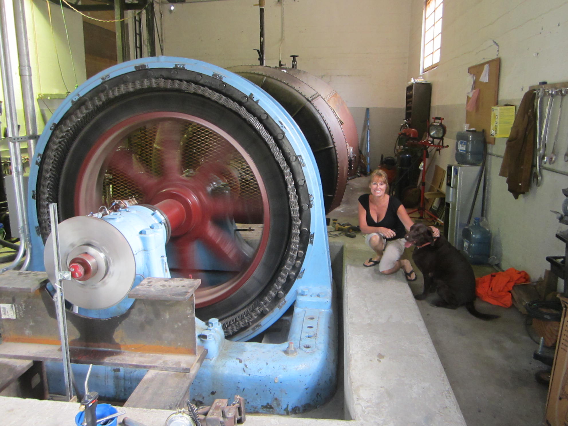
Here, Karen is inspecting the three TG sets at Tannery Pond HEP. Notice the main thrust bearing support plate recently installed beneath the No. 2 Unit.
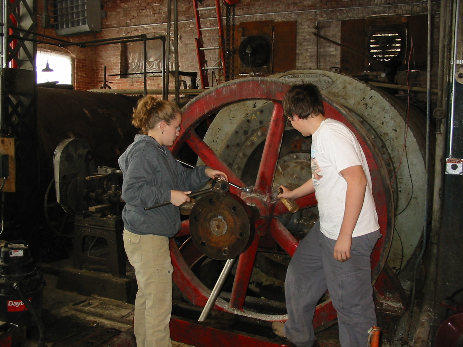
Will and Celesty are removing the flywheel from Woronoco No. Two. In this photo, Will is 13 and Celesty is 15. 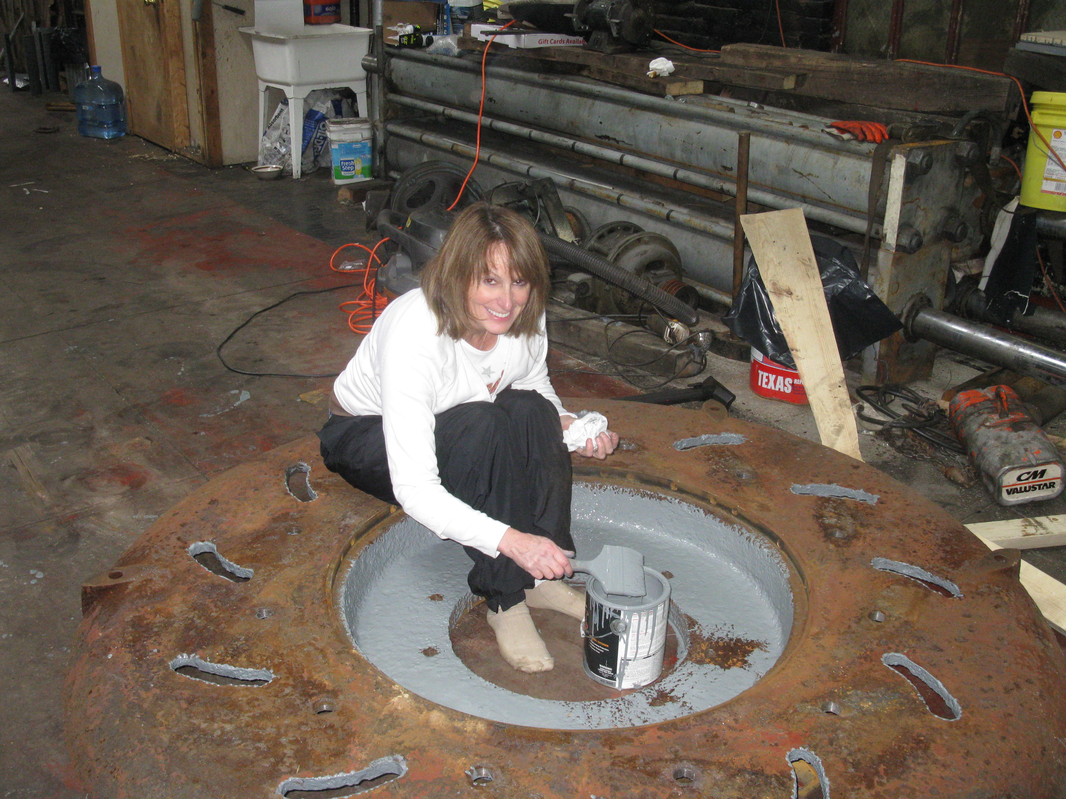 Here, Karen is painting the crown cover of one of the two Leffel 43" Type "F" camelback turbines that will be installed as the No.One Unit at Indian River HEP. I previously chased the threaded holes, de-scaled the surfaces and wire wheeled the surfaces. Karen is a great sport and the only SRHOCO spouse who has ever done any physical work on our powerplants! |
|
February 21st,
2011, added Byron McCoy's 1952 paper on the "Evolution of
Hydraulic Prime Movers". Mr. McCoy was a water power engineer
for Charles T Main Company of Boston, Massachusetts during the
1950s and 1960s. Please enjoy it:
Byron McCoy<<< click here!!
My good friend, Ian Smith, posing in front of the Hillsborough, N.H., Henry Obermeyer, chain drive turbine. His father, Ken Smith, his brother Marshall Smith and he formed Smith Alternative Energy in 2009. They have completed many interesting hydro projects in the interim. Please see their site: www.smithtest.com <<< click here to peruse their photo albums. Please call them at 413-427-4236 or 508-867-6976 for any hydro related work.
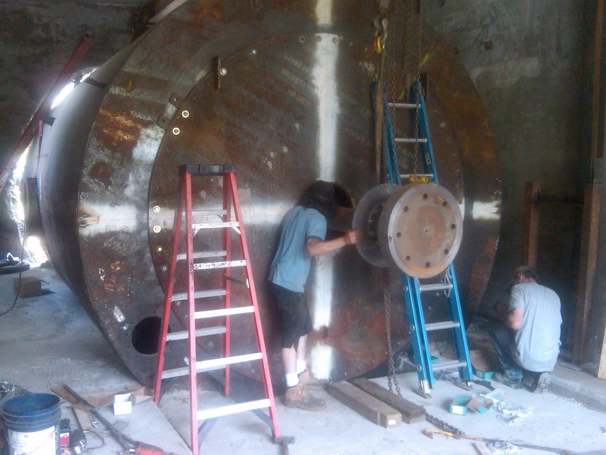
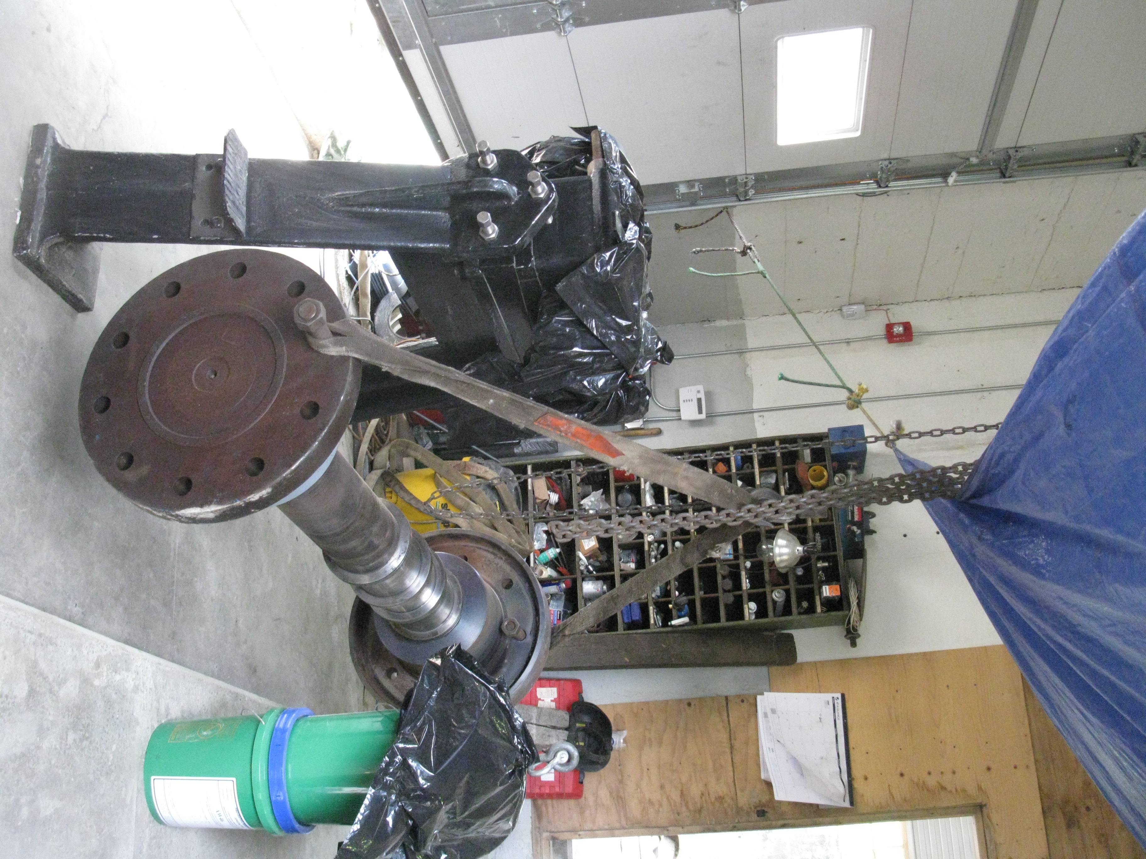
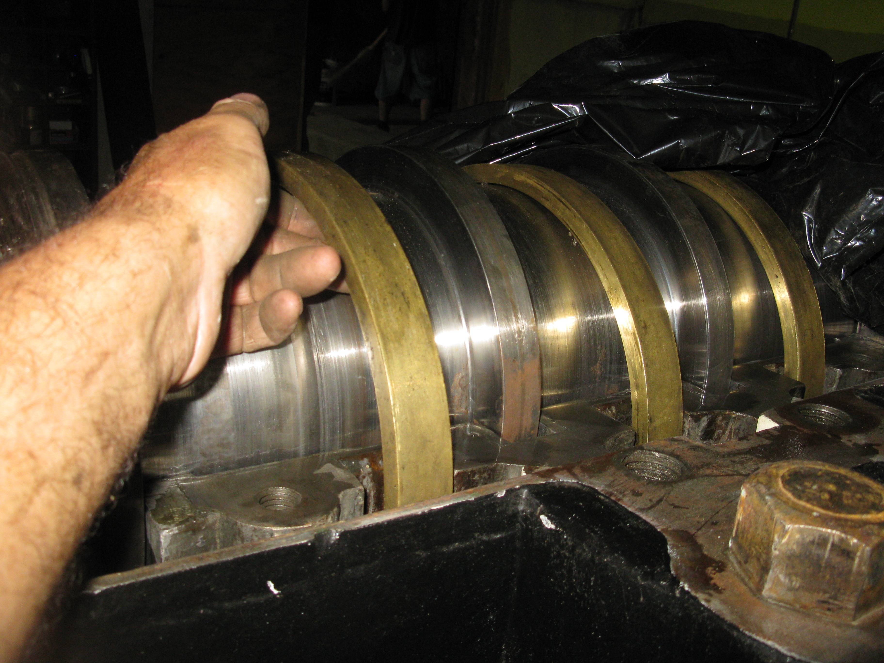
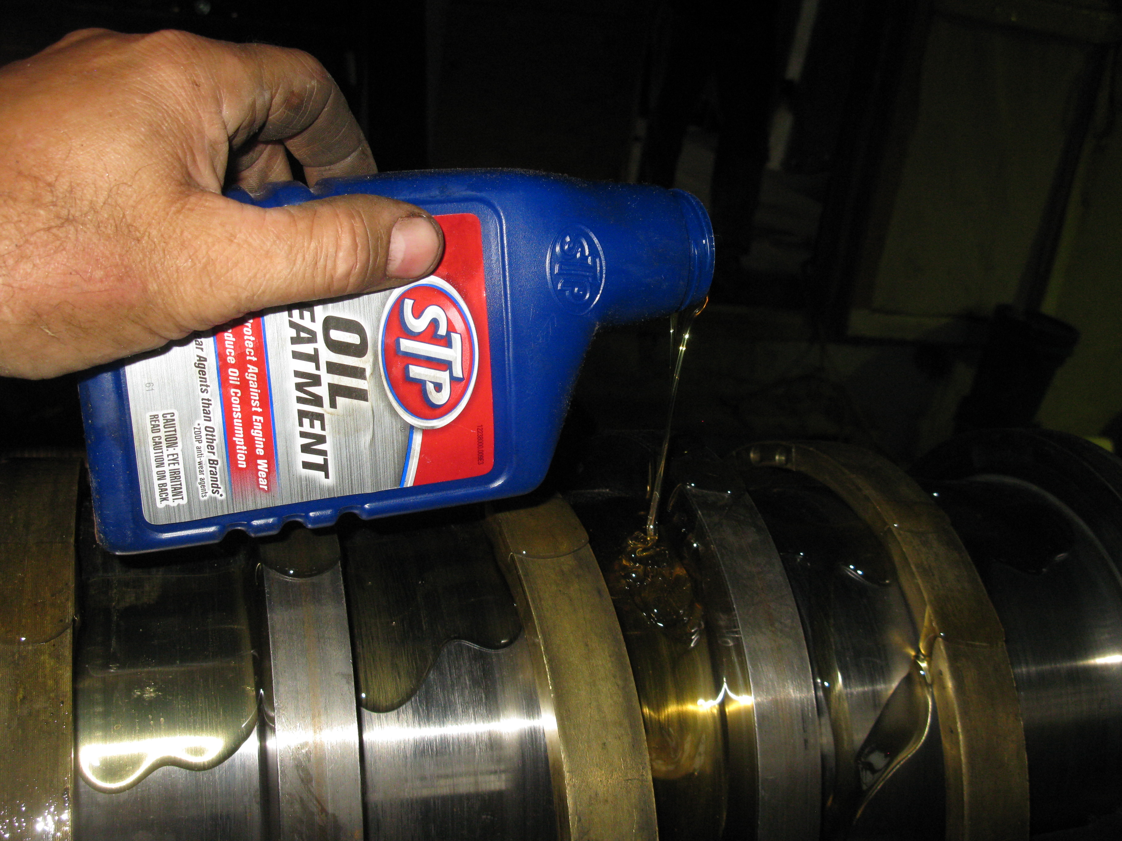
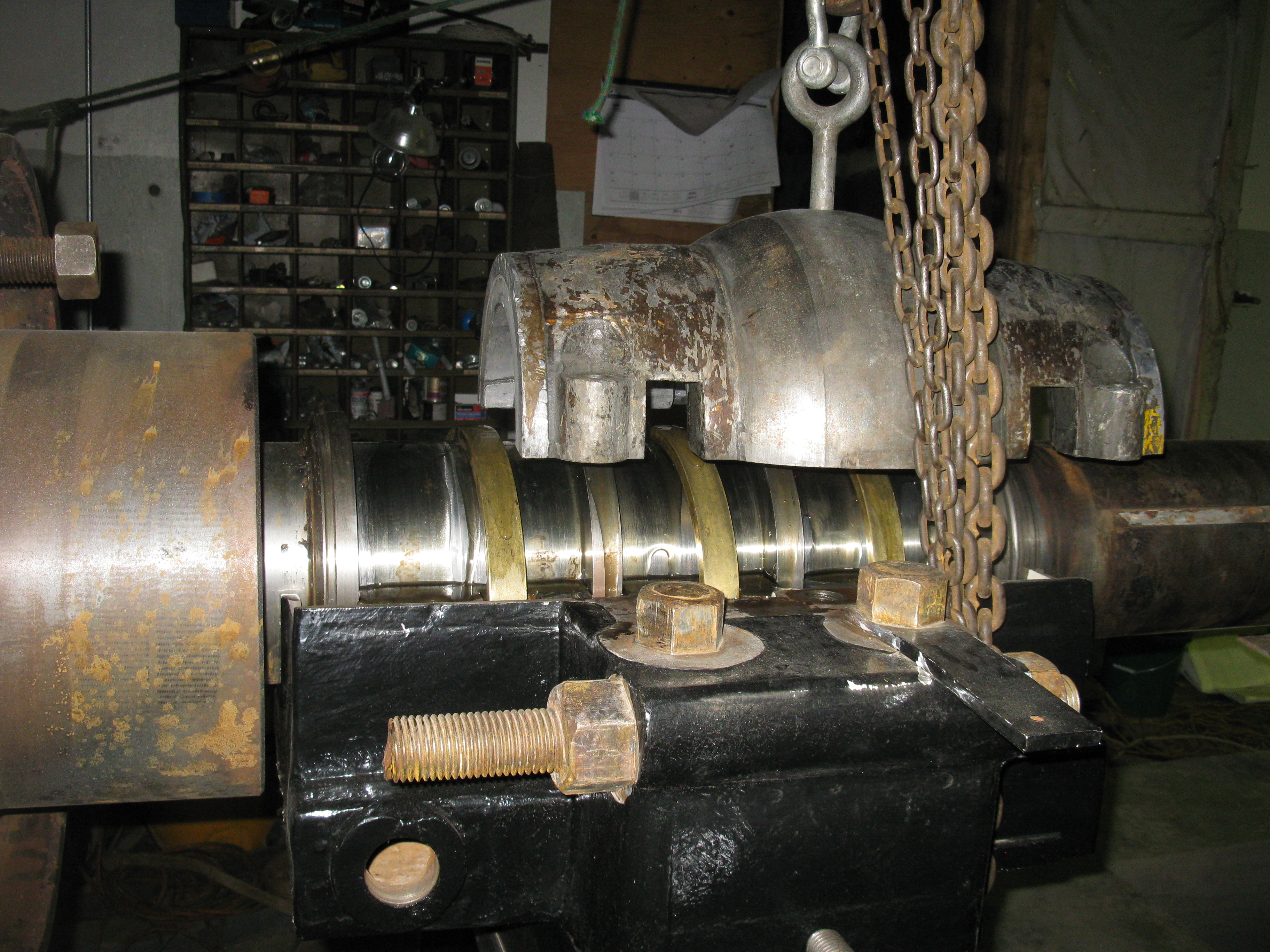
Here, you see the top cover of the famous, Henry Obermeyer, chain drive turbine removed. Note the silent chain looped over the upper, output shaft. Henry is a prolific inventor/designer. He is now manufacturing a unique Bascule Gate that has been installed worldwide. See his unique gate system at: http://www.obermeyerhydro.com or call him at 970-568-9844 January 30th, 2011 Revised draft tube web page. Added photos of draft tube construction and installation. Rigging a large generator <<<<<< click here Fitting a large runner shaft <<<<< click here
|
|
|