|
Wynoochee Hydro
Mechanical Repairs Fall 2014 to Spring 2015
During a recent attempt
to eliminate a tenacious oil leak on the turbine generator at Wynoochee, a
number of problems were discovered and repaired. These included failed welds
inside the generator support structure, a failed rubber turbine guide bearing, a
damaged turbine shaft seal, silt plugs inside the heat exchangers and drain
lines, and a worn generator shaft support that allowed the shaft to swing like a
pendulum. The 15 megawatt Wynoochee Electosila Generator and LMZ turbine, which
were purchased shortly after the fall of the Soviet Union, were installed in
1994.
The 40,000 pound upper bracket with the broken welds was removed and sent to
Thompson Metal Fabrication. They ground out the damaged welds, replaced them and
baked the piece in a large oven to relieve any stresses. It was subsequently,
shipped to A.F. Dick Machine shop to have its surfaces trued up, sandblasted and
receive a new coat of paint.
Fortunately, a new rubber bearing that had been preserved for 20 years was
located in the Wynoochee store house. The old bearing was removed and the new
bearing was installed.
The fretted, copper interference rings that supported the generator shaft were
replaced with new bronze rings.
Tacoma Power hired HCMS a contractor that specializes in hydro generator work, to
re-assemble and balance the unit. They worked closely with Tacoma Engineers,
Cushman staff and NAES mechanics to assemble the unit. After the assembly was
completed an attempt to balance the unit was made. The assembly team did such a
great job that the unit was deemed balanced without the addition of balance
weights. The unit was restored to service March 19.
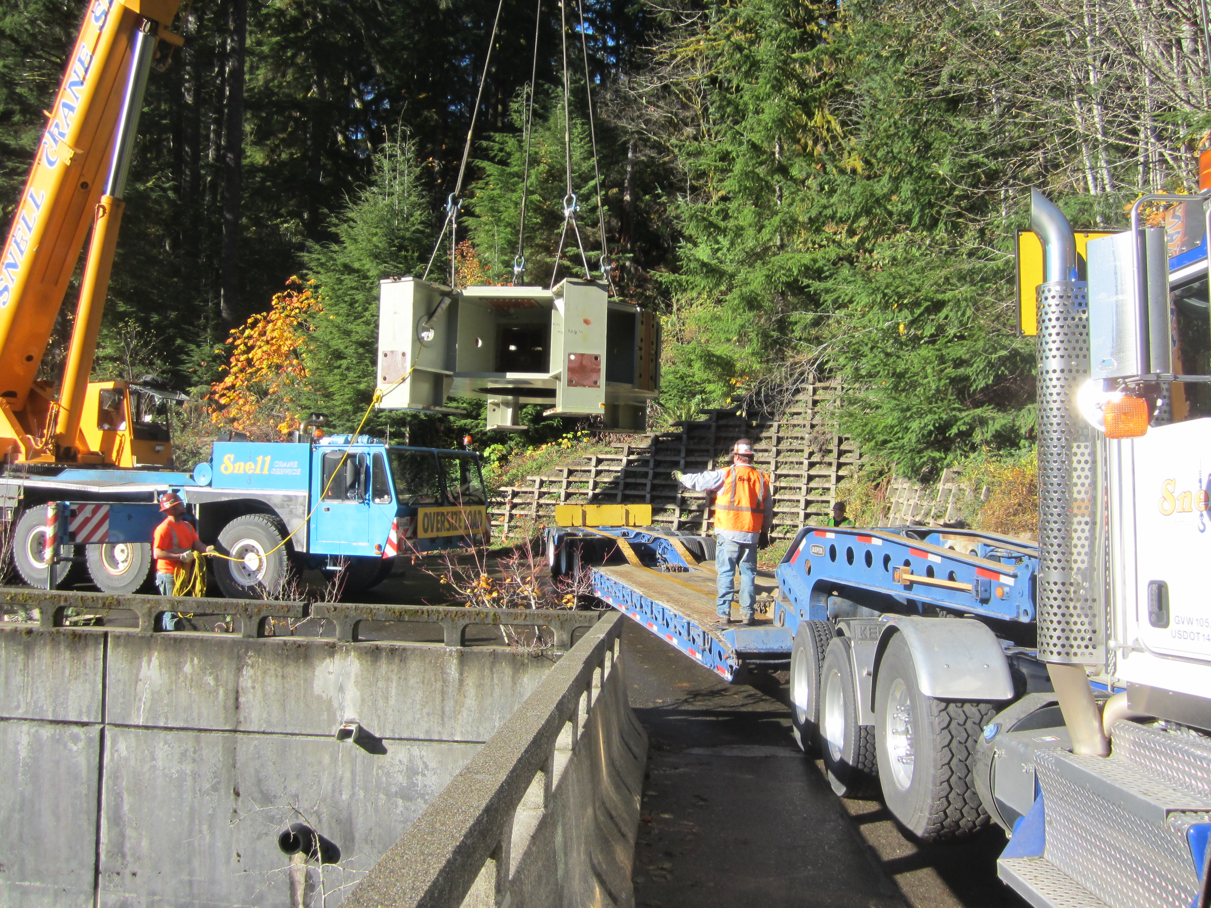
Figure 1: Flying out the damaged generator
bracket on Christmas Eve.
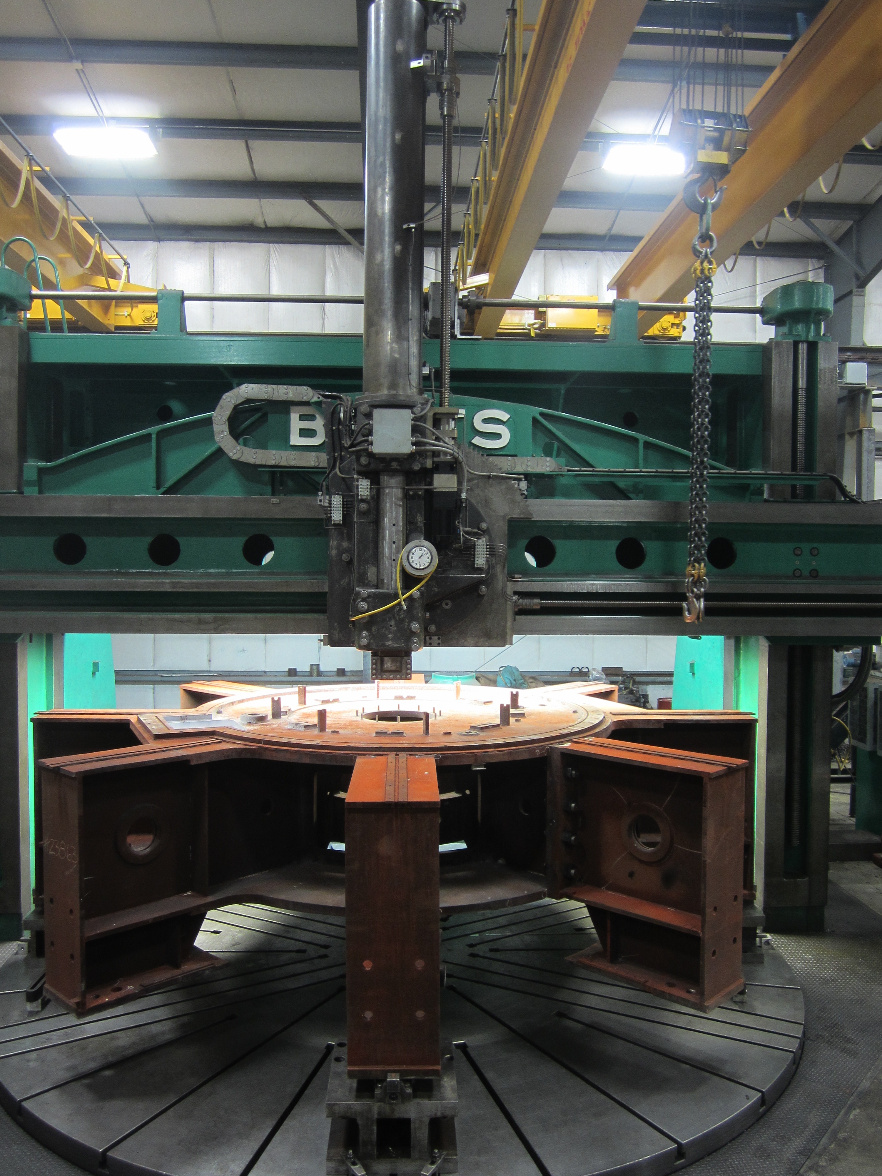
FIGURE 2. The 35,000 pound bracket sits
on the 20-foot diameter turntable at A.F. Dick Manufacturing Machine Shop in
Astoria, OR (Contact Art Dick at 503-458-6292). Art Dick was awesome and allowed
our bracket to be slipped in the schedule between an order for rocket bodies for
NASA and a giant hydro generator shaft from CA.
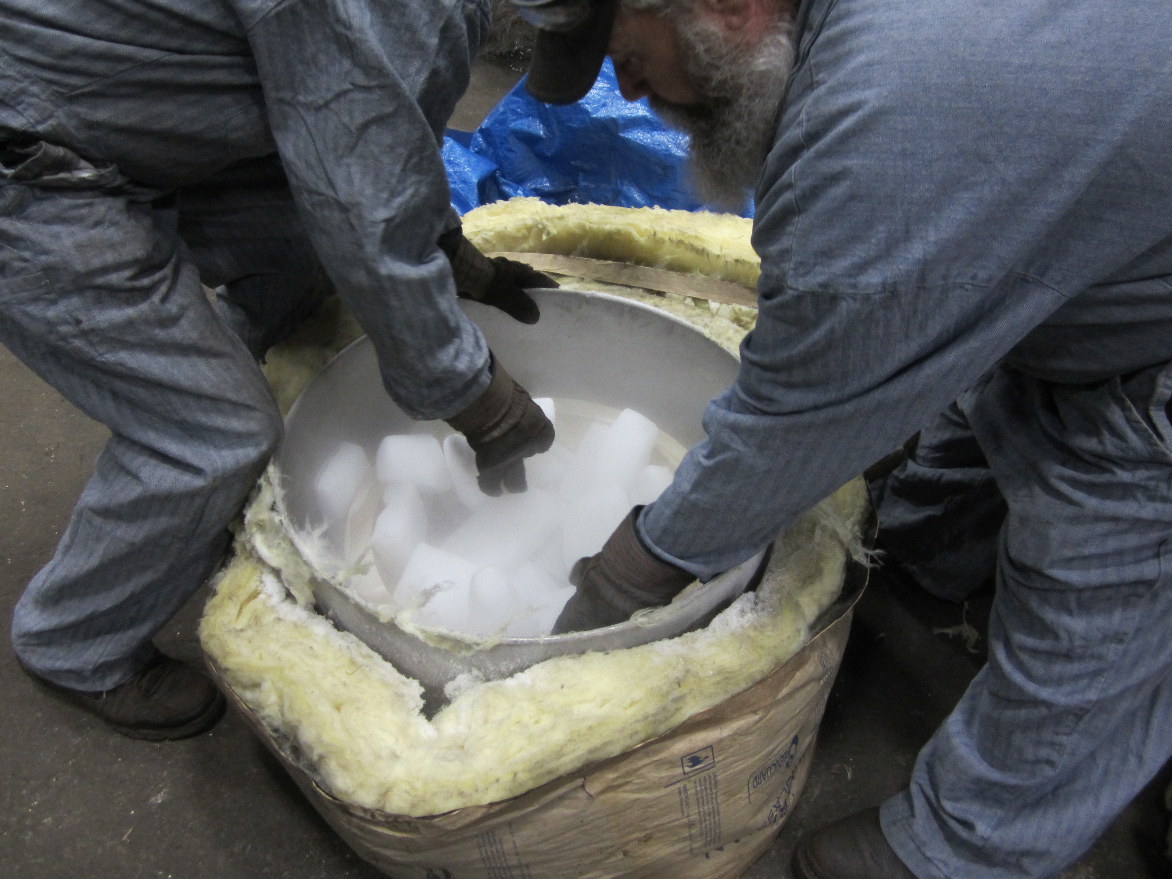
Figure 3. A chilling effect: The bronze
interference ring is cooled with dry ice to shrink fit for installation.
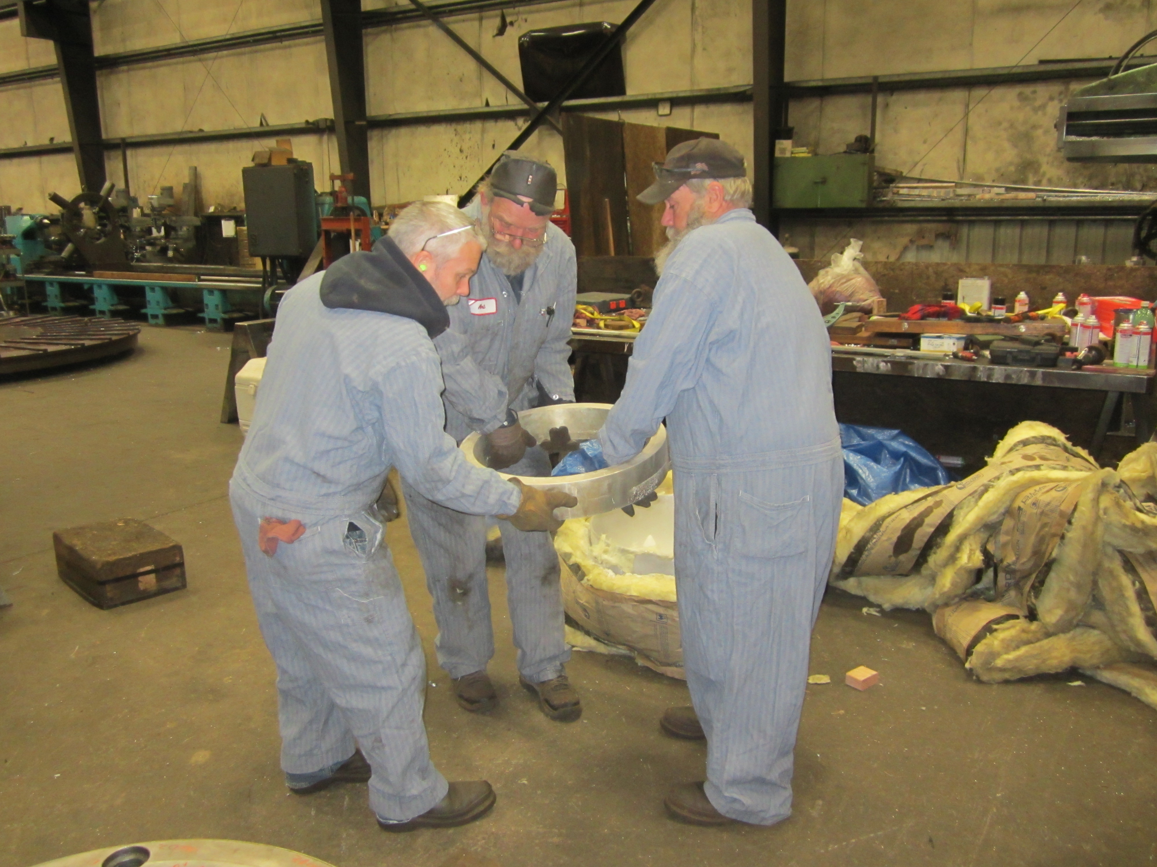
Figure 4. Carrying the sub chilled
interference ring to the thrust block for insertion. Art Dick is in the center.
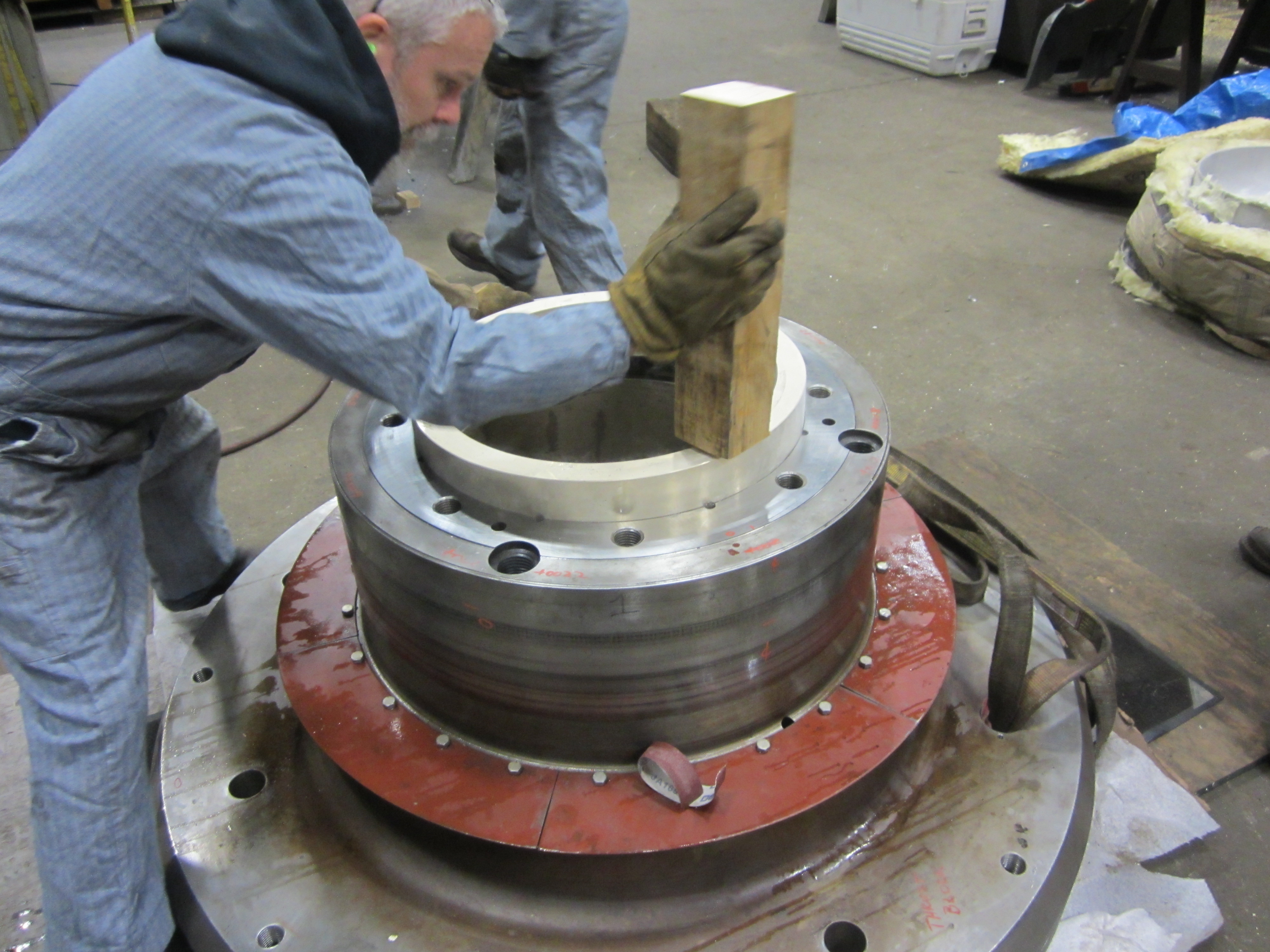
Figure 5. Inserting the sub chilled
bronze rings into the thrust block.
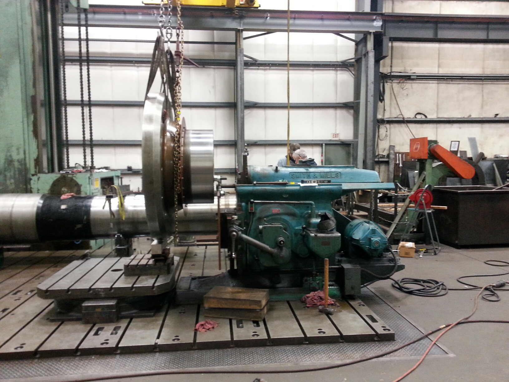
Figure 6. Machining the vertical keyway
through the surface of the new bronze interference rings with a large shaper.
The interference fit of the bronze ring in the steel thrust block is 0.009
inches. The bore of the block was subsequently machined on the Betz Boring Mill
to a o.oo3 interference fit between the bronze bore and the steel generator
shaft.
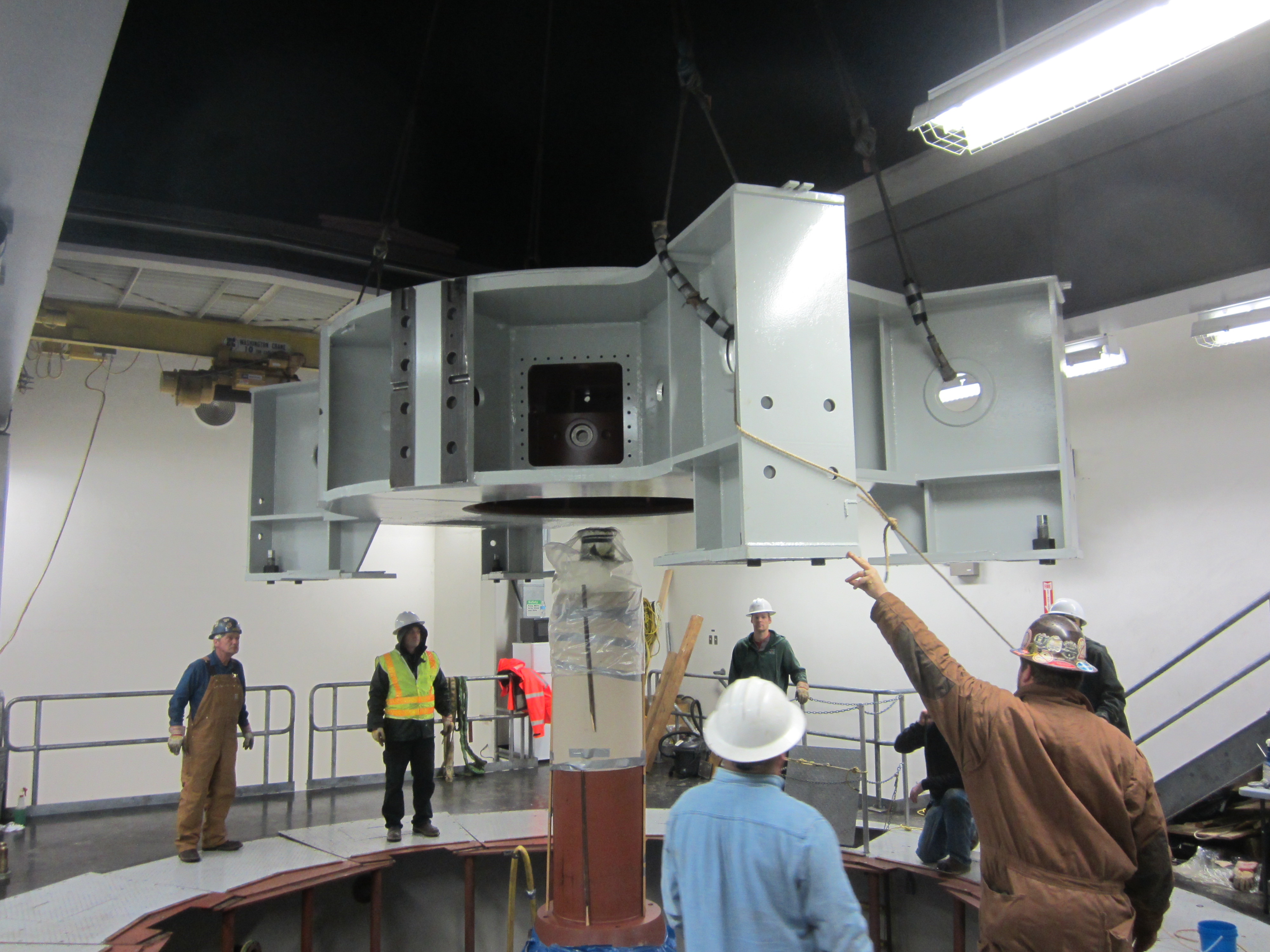
Figure 7.Flying in the restored
bracket. Note the sun has not come up.
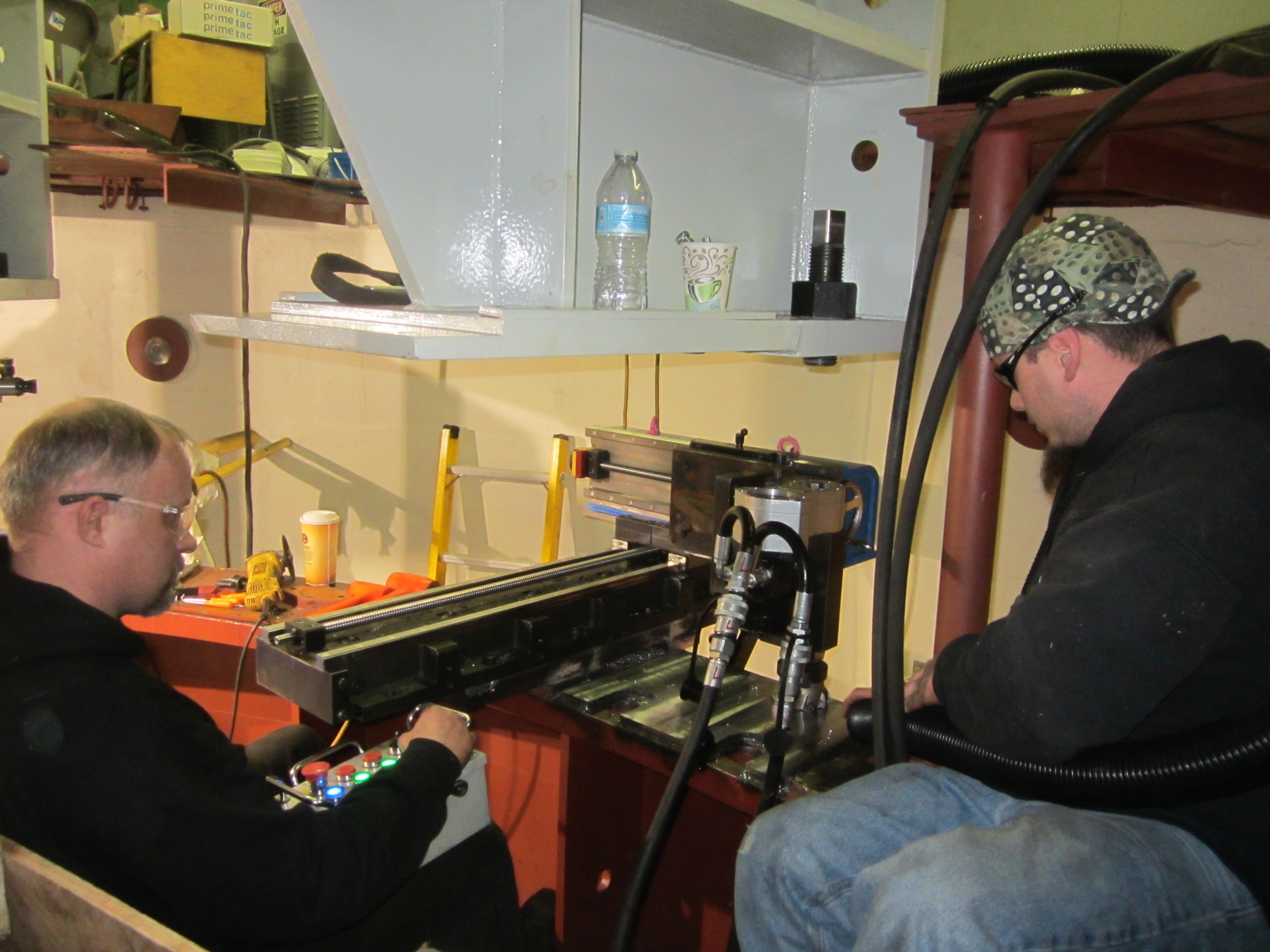
Figure 8. Insitu machining of the new,
welded on, large generator shim. We replaced the 8 stacks of layered shims we
found beneath the feet with on large shim.
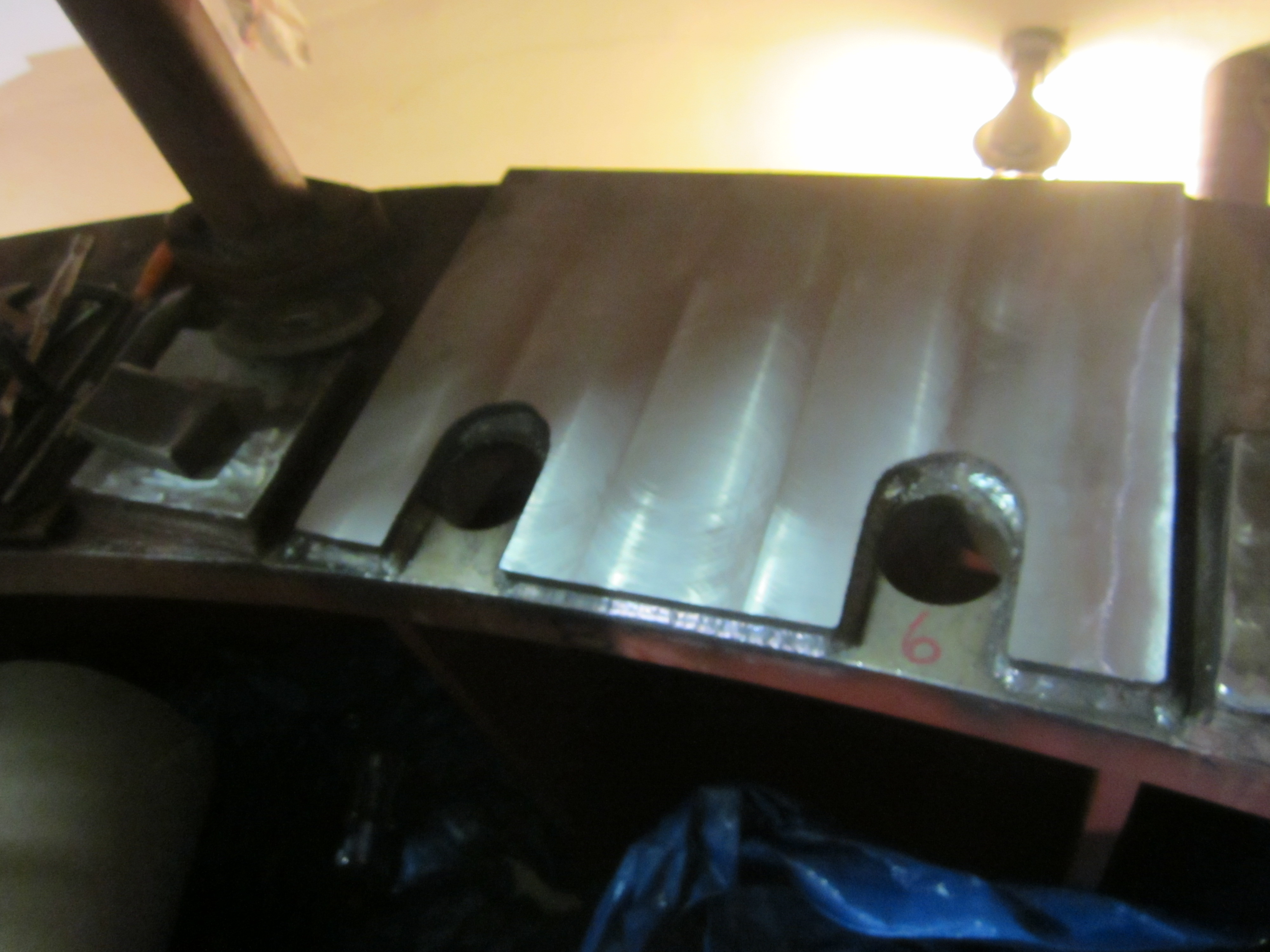
Figure 9. Finished mounting pad (large
shim welded on).
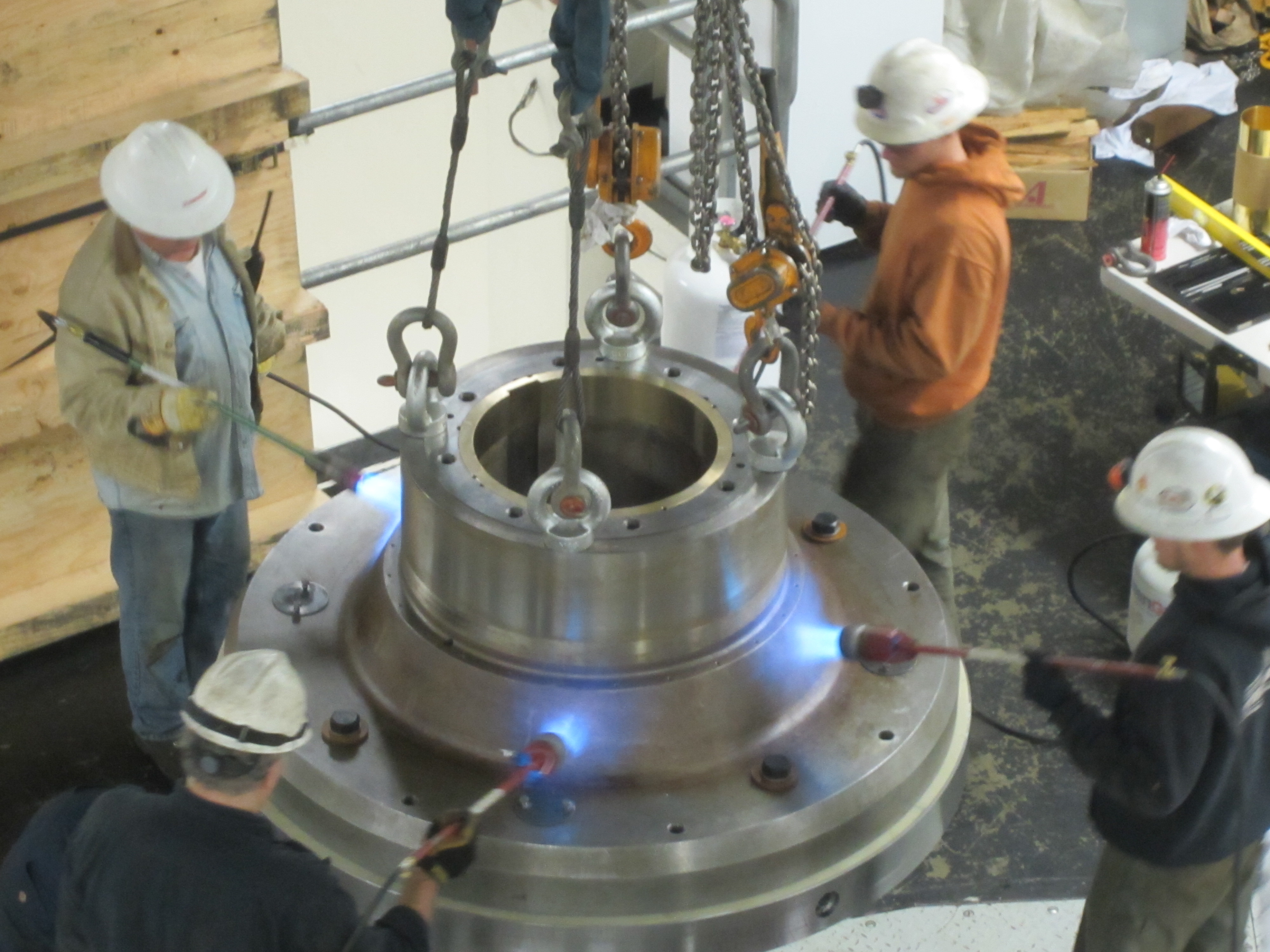
Figure 10. In the hot seat, the
generator thrust block is heated to allow it to slip overthe generator shaft.
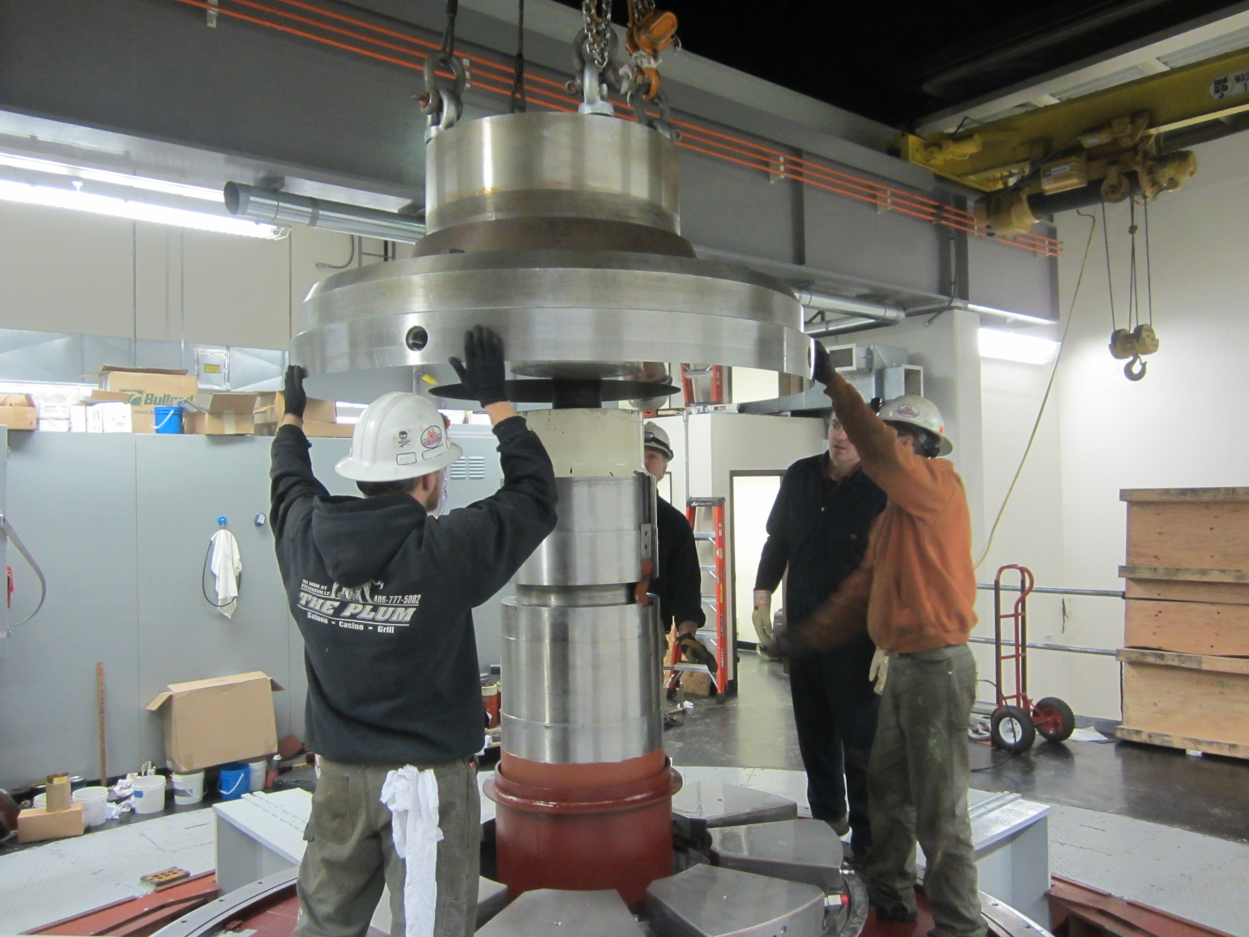
Figure 11. Lowering the heated thrust
block onto the generator shaft.
|  GREEN
GREEN